The famous Chrysler DRB III
Checking out a DRB III
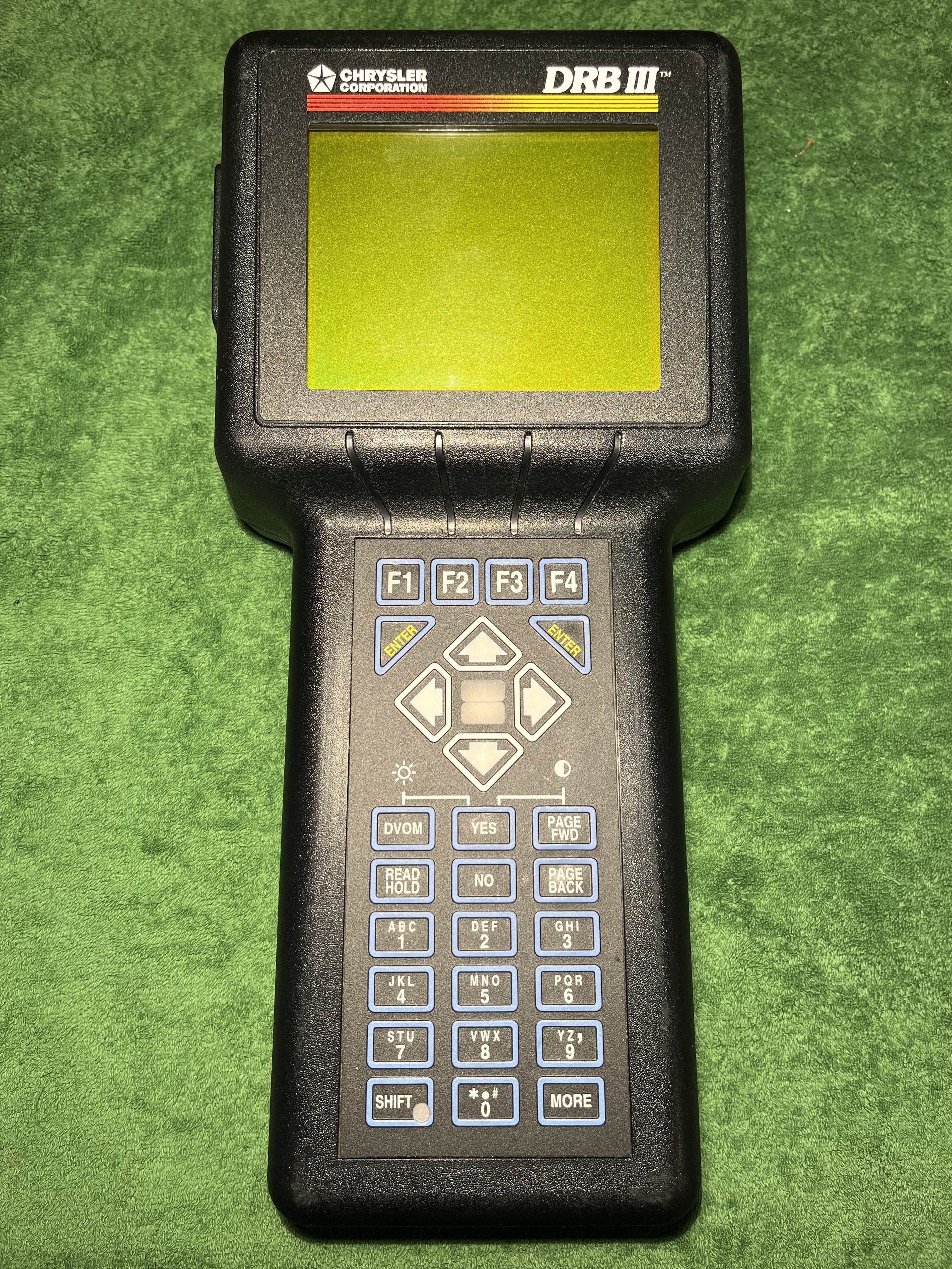
Let’s have a look at the successor of the Chrysler DRB II diagnostic device, the DRB III. It pioneered somewhere around 1993.
Quite some things have changed. The DRB III is much bigger, the keyboard changed, the display is larger and it comes in a nice leather case. It has a (annoyingly loud) fan and the display protector could be swapped to a non-glare version.
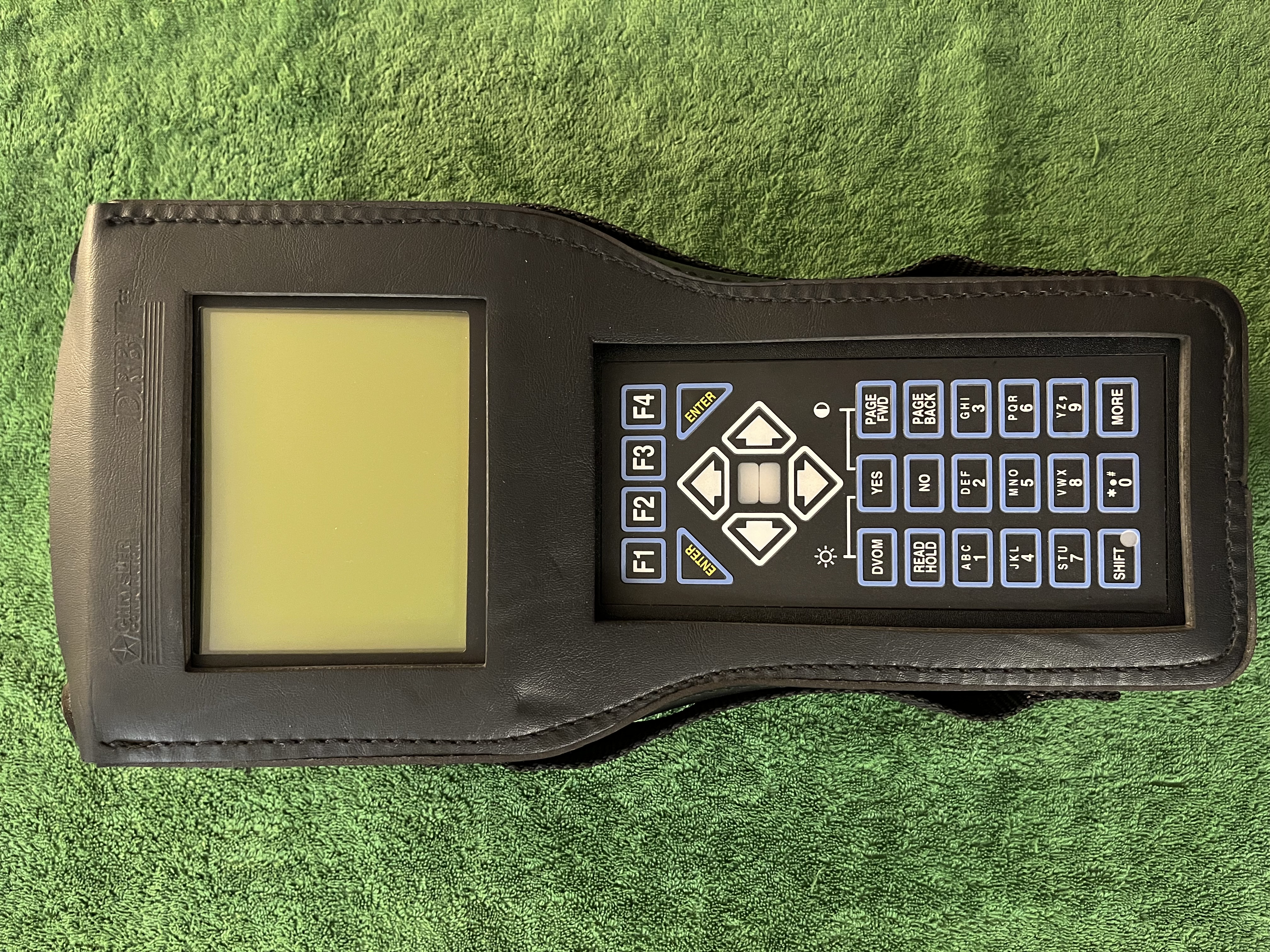
The leather case alone is quite a piece. It has a hook to hang it onto stuff.
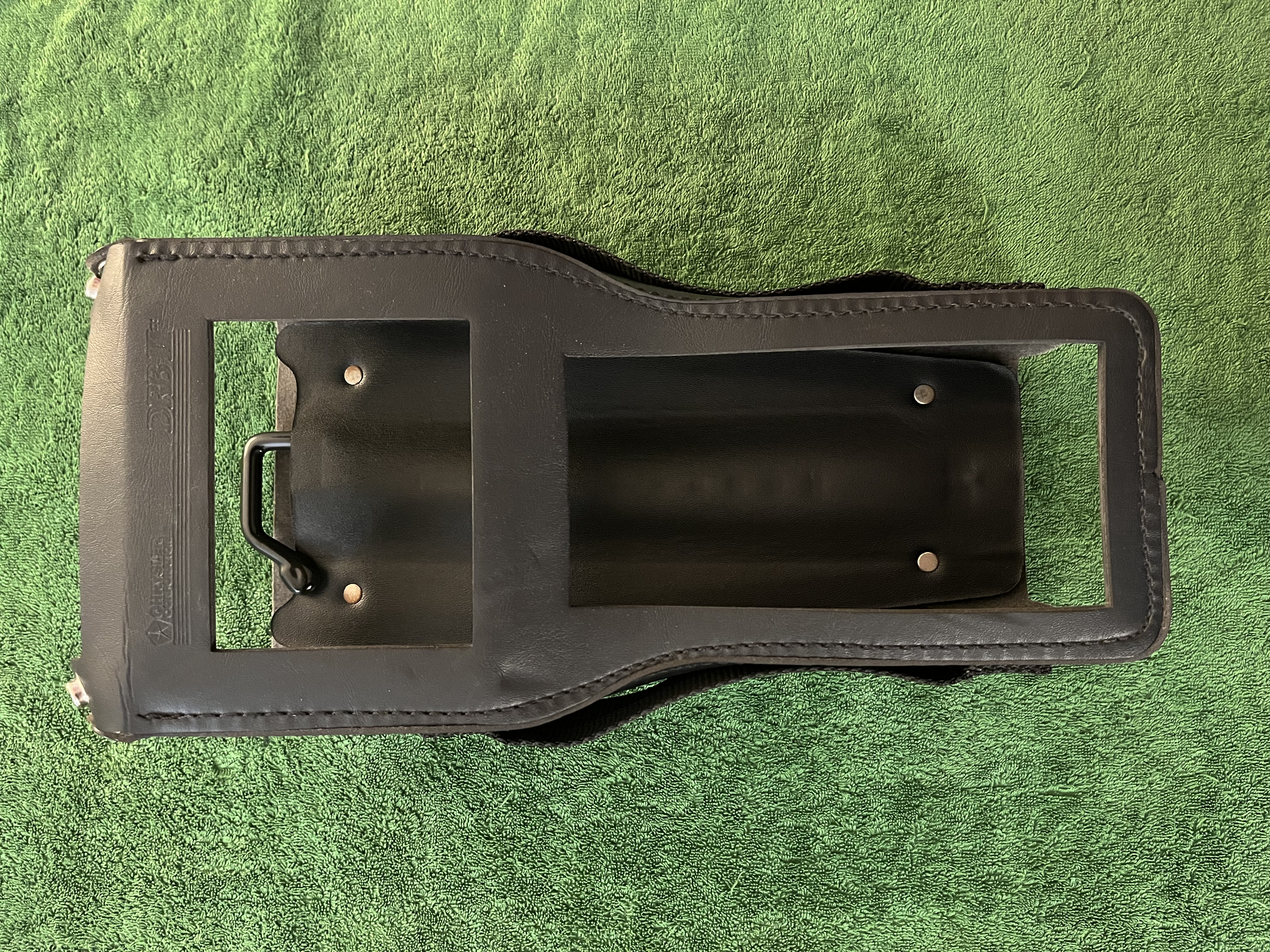
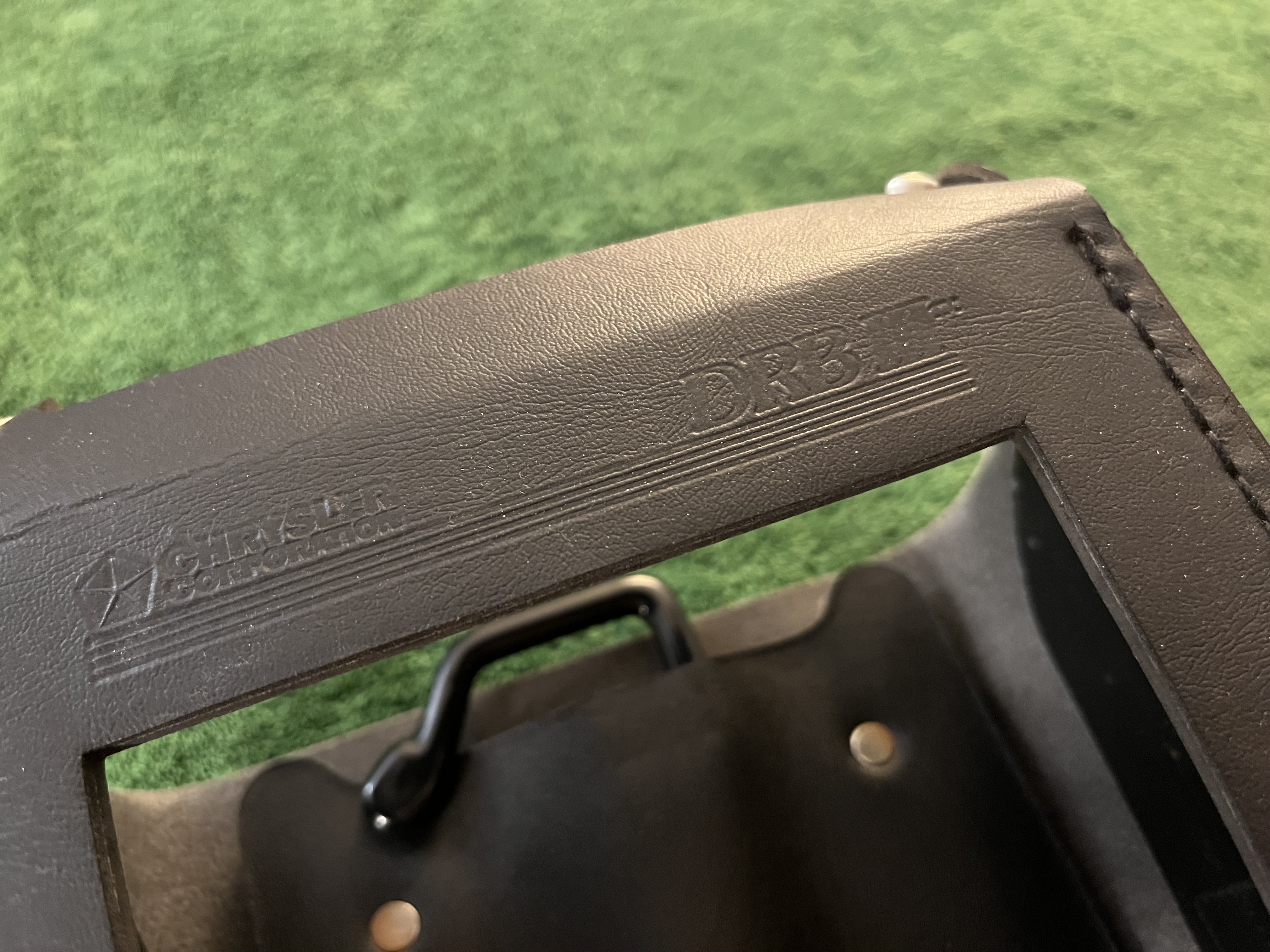
It even has the “Chrysler Corporation” logo and “DRB III” embossed into the leather.
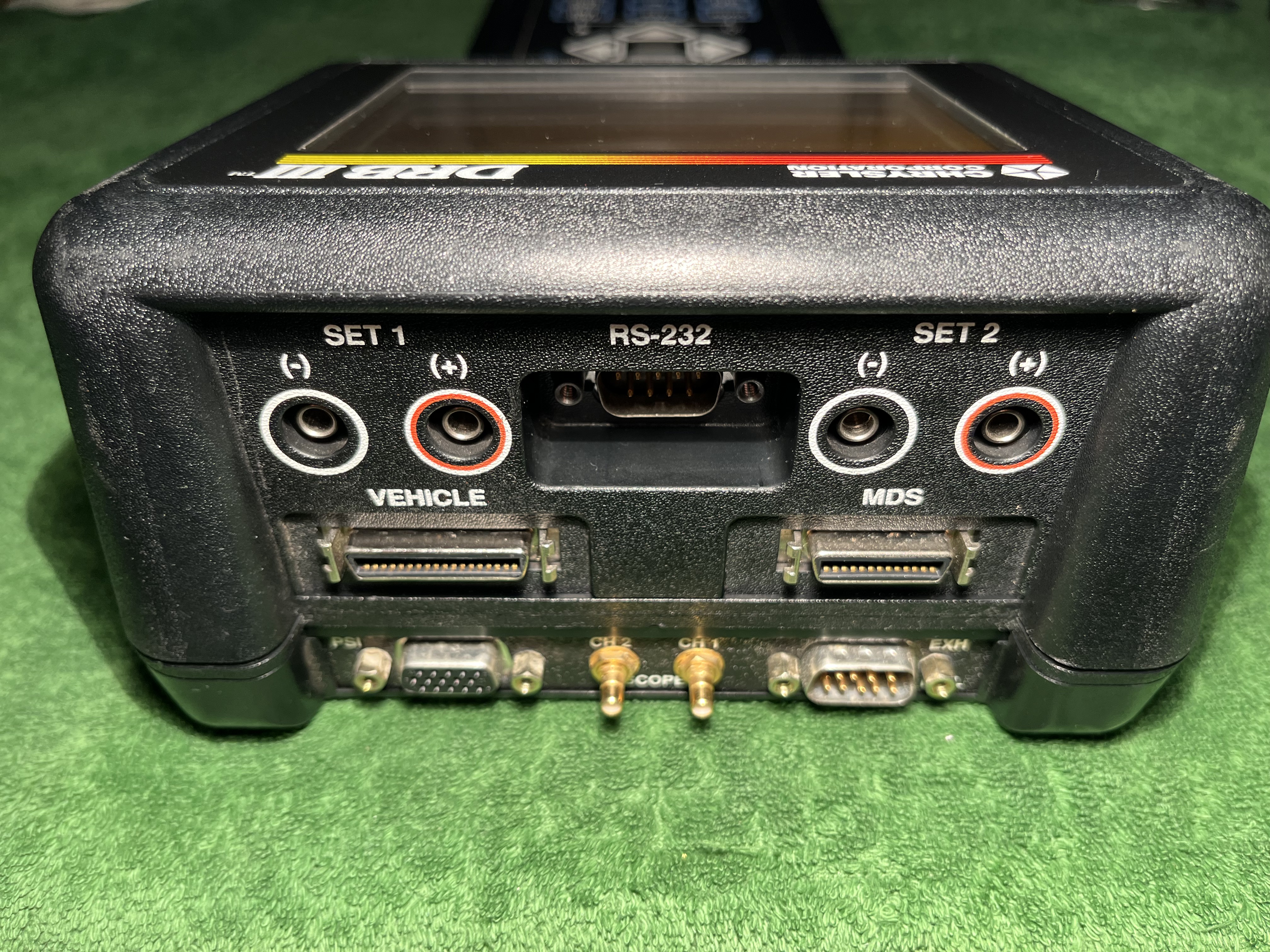
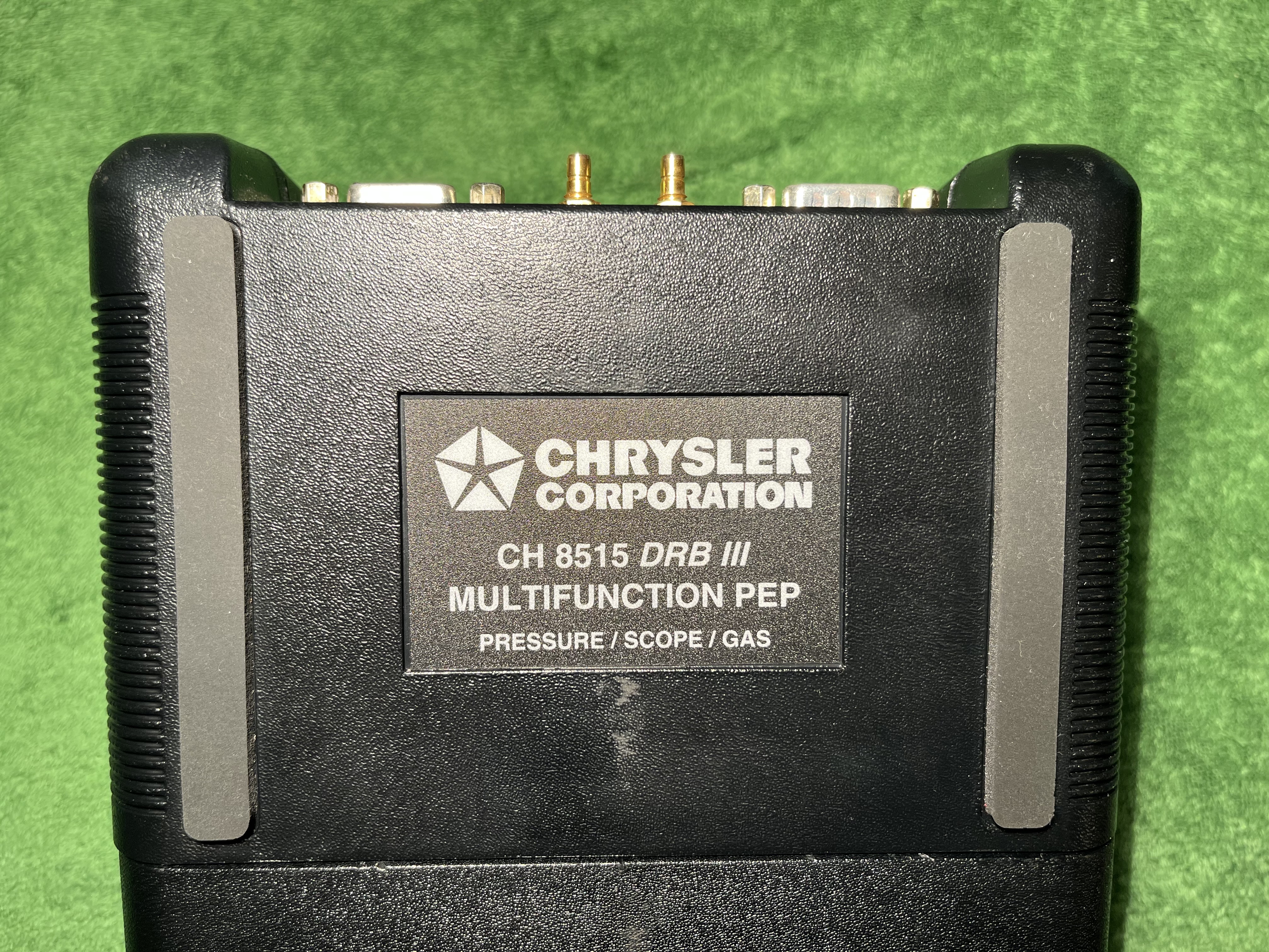
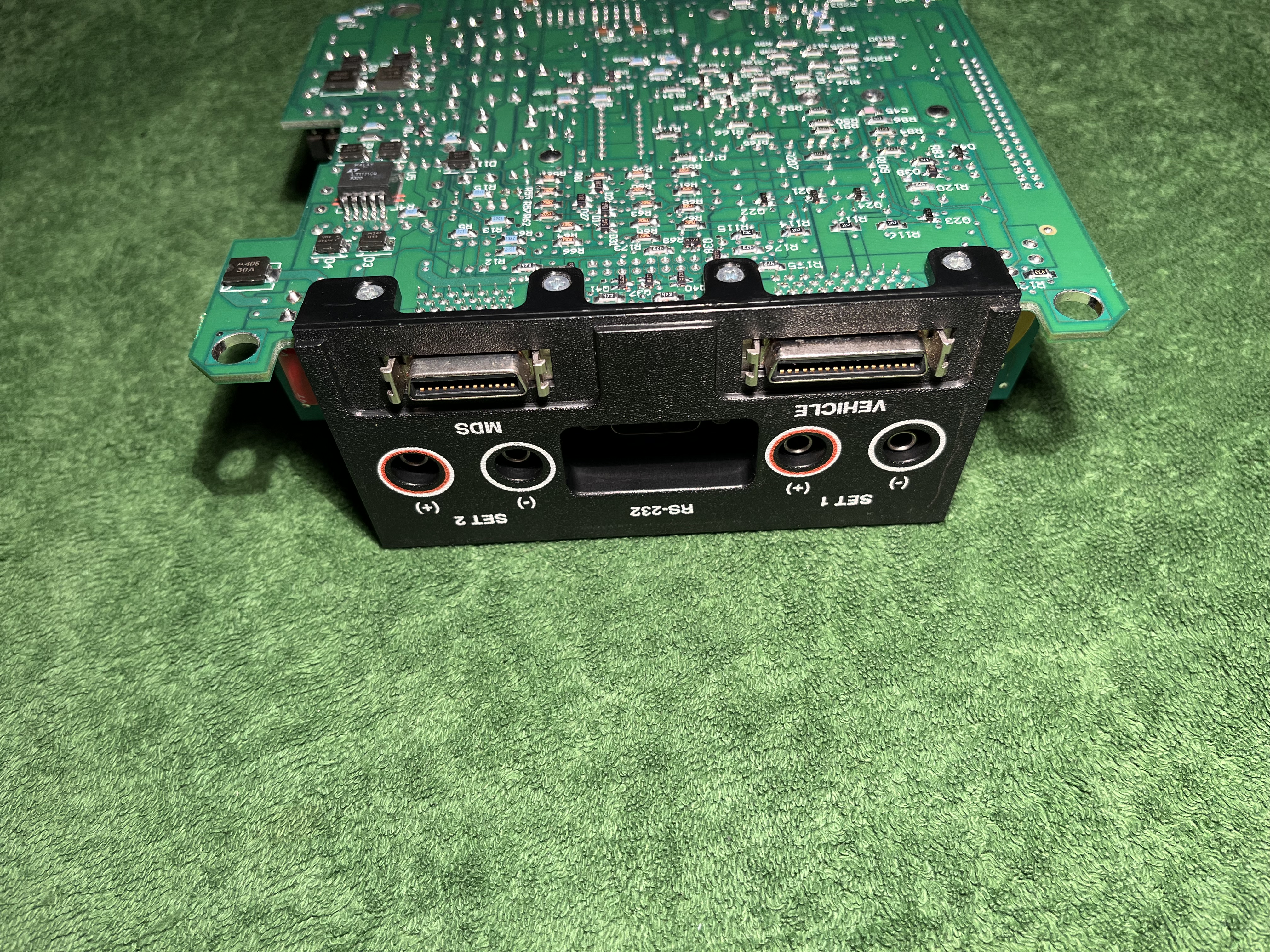
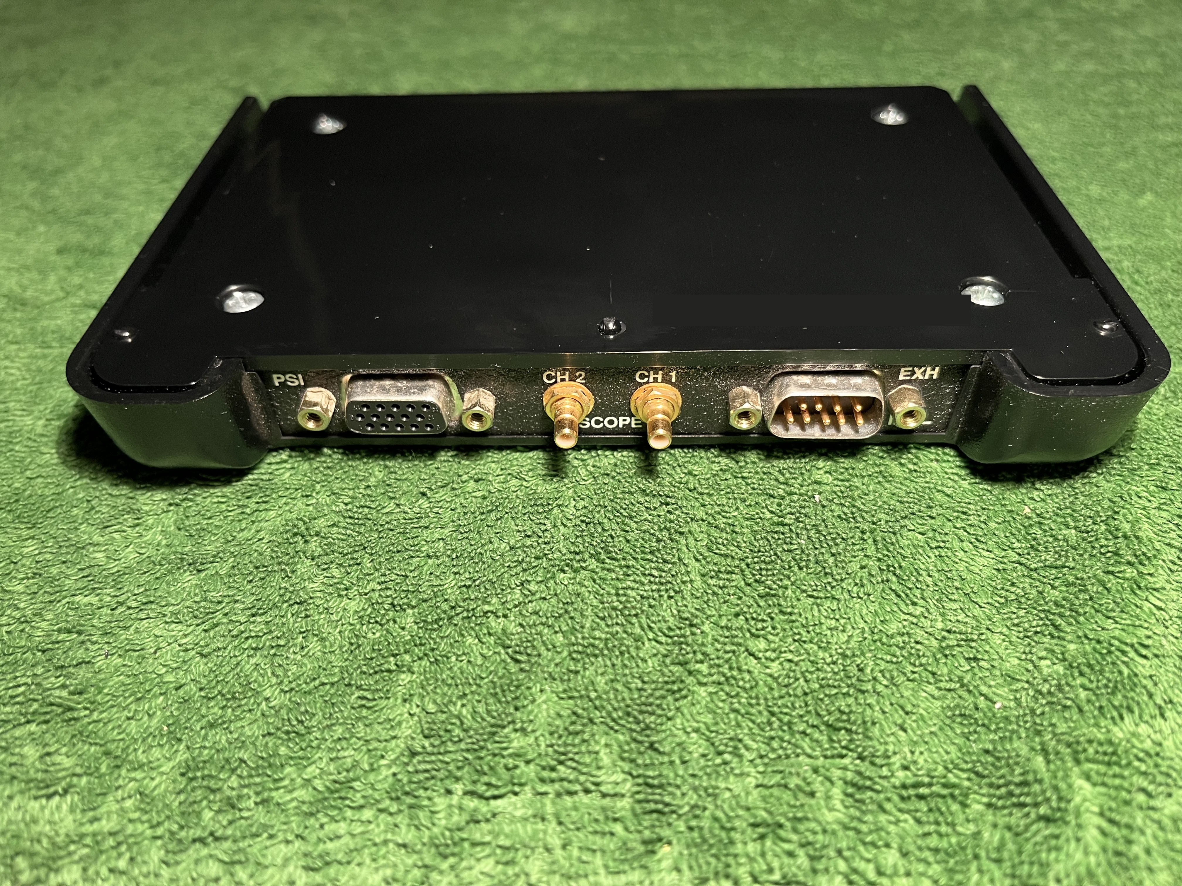
More inputs found their way into the the DRB III. Connectors for test-leads, RS-232 and even pressure connectors. It also has a dedicated connector for the MDS, the Mopar Diagnostic System. The pressure scope and a few more connectors are located on an extra module, the PEP module (Peripheral Expansion Port).
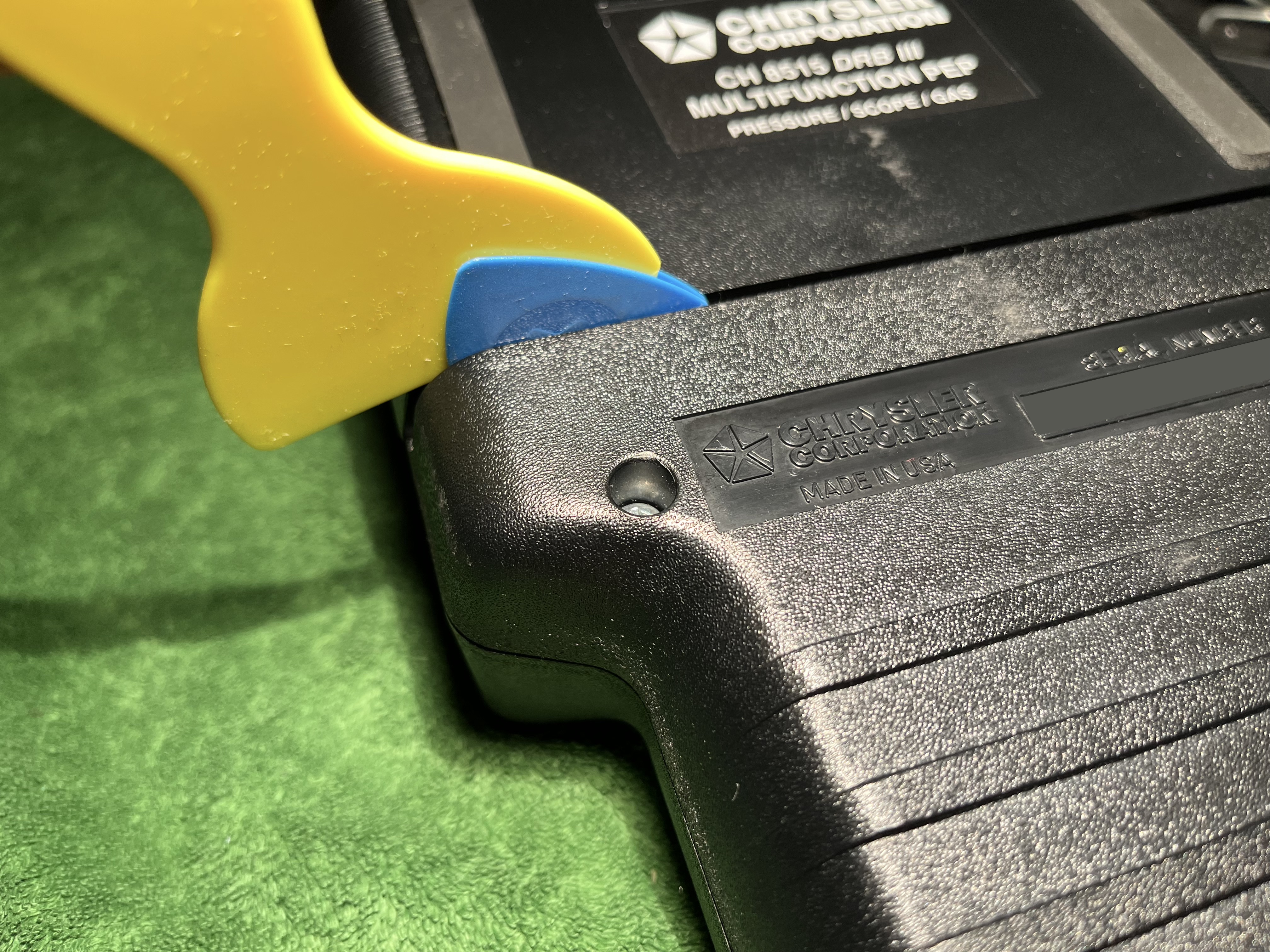
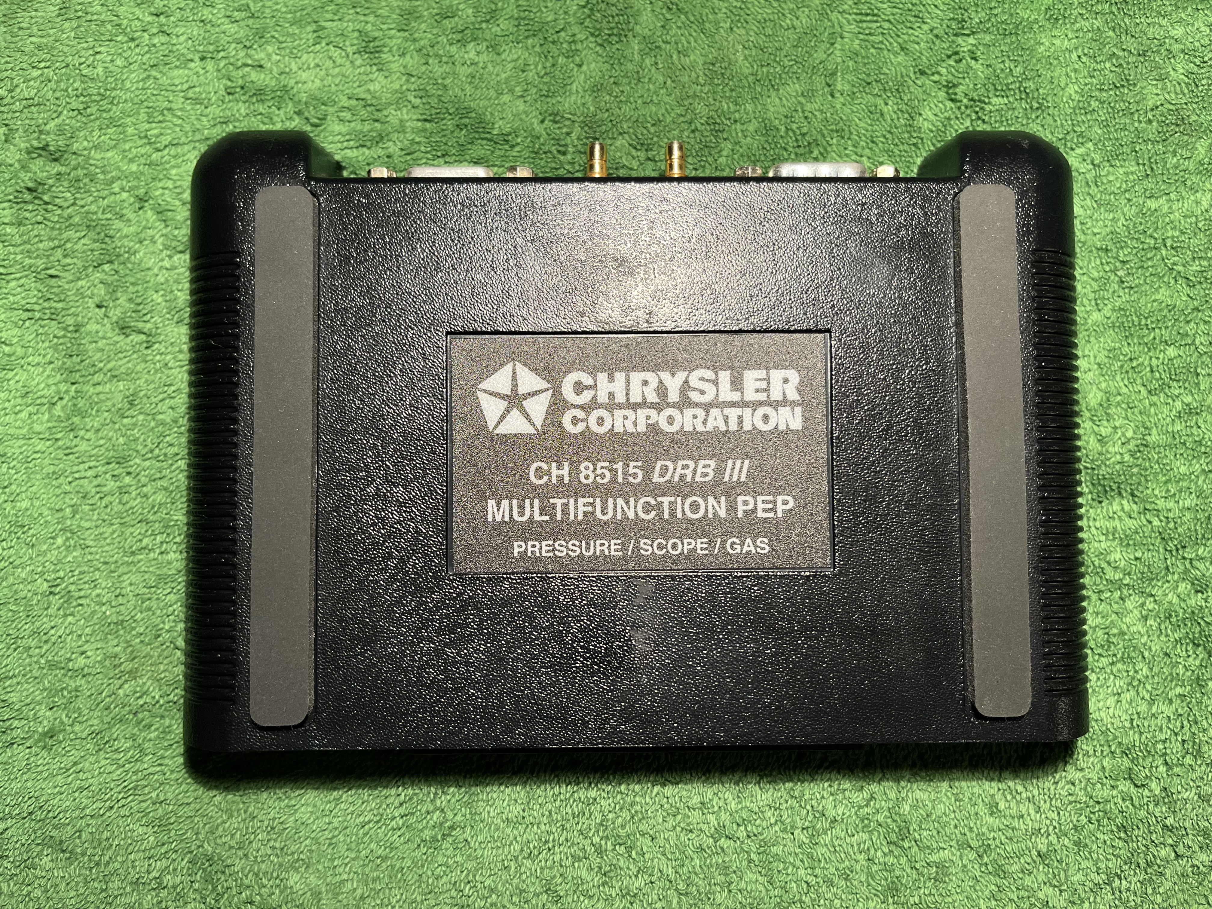
This PEP module slides onto the back of the DRB III and extends the functionality of the device and seems to be introduced around 1996. The partnumber is CH8515.
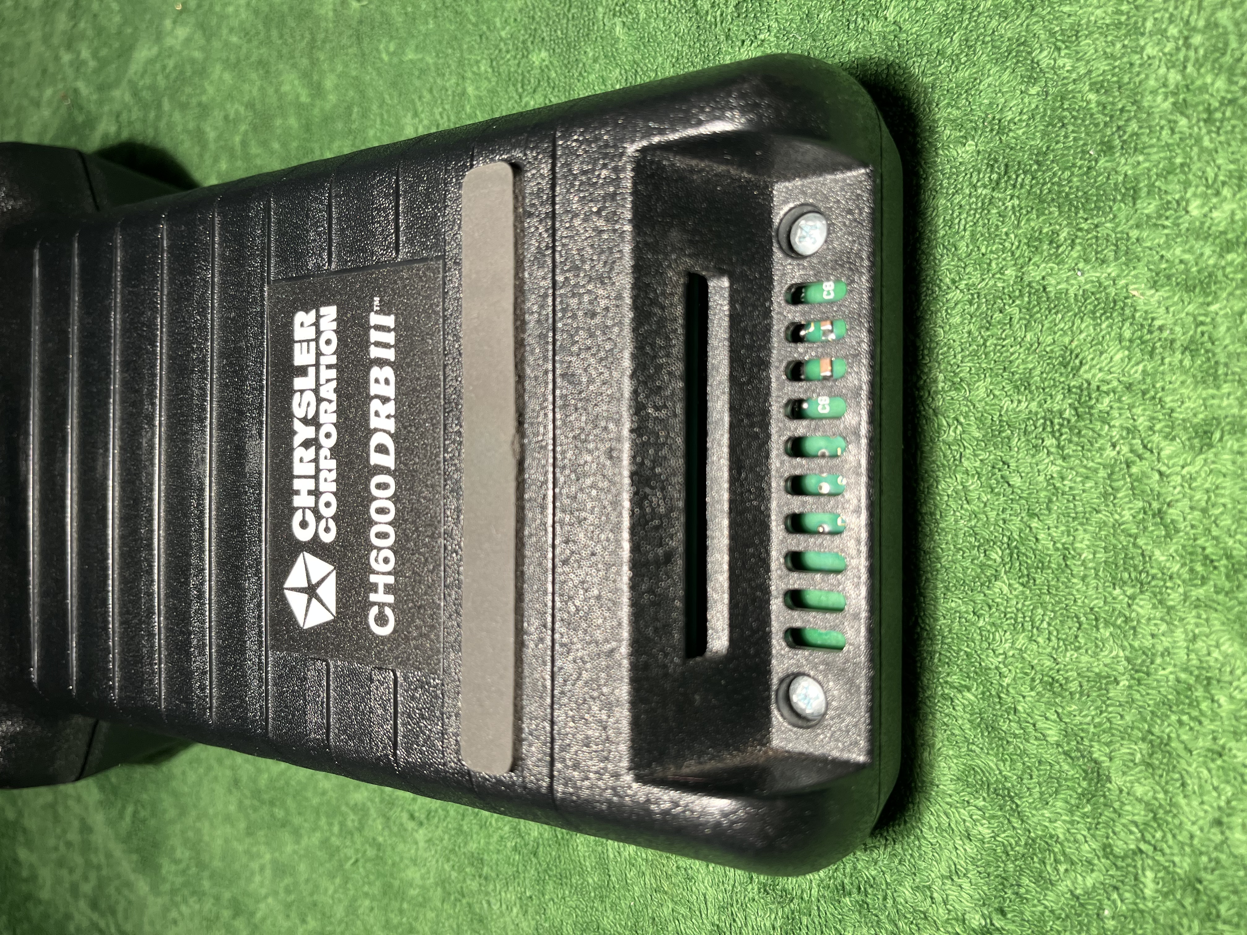
Speaking about partnumbers, the DRB III’s P/N is CH6000. At the bottom of the device a PCMCIA card can be inserted.
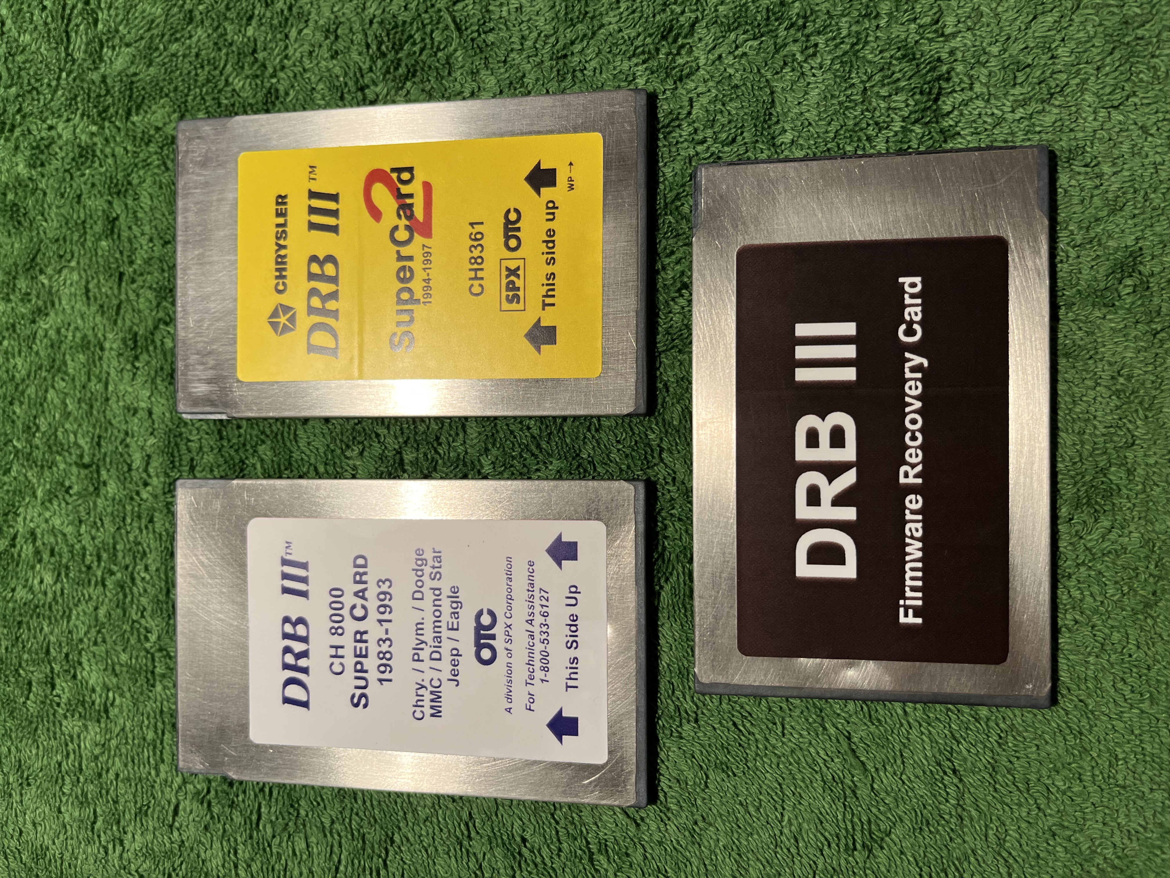
These are three examples for the PCMCIA cards. The SuperCard I covers the years 1983 to 1993 and has the P/N CH8000. The SuperCard II is applicable to years 1994 upto 1997 and has the P/N CH8361. A firmware recovery card can be used to fix any issues with the firmware on the DRB III itself. Besides these three, there are quite a few numbers of different cartridges out there.
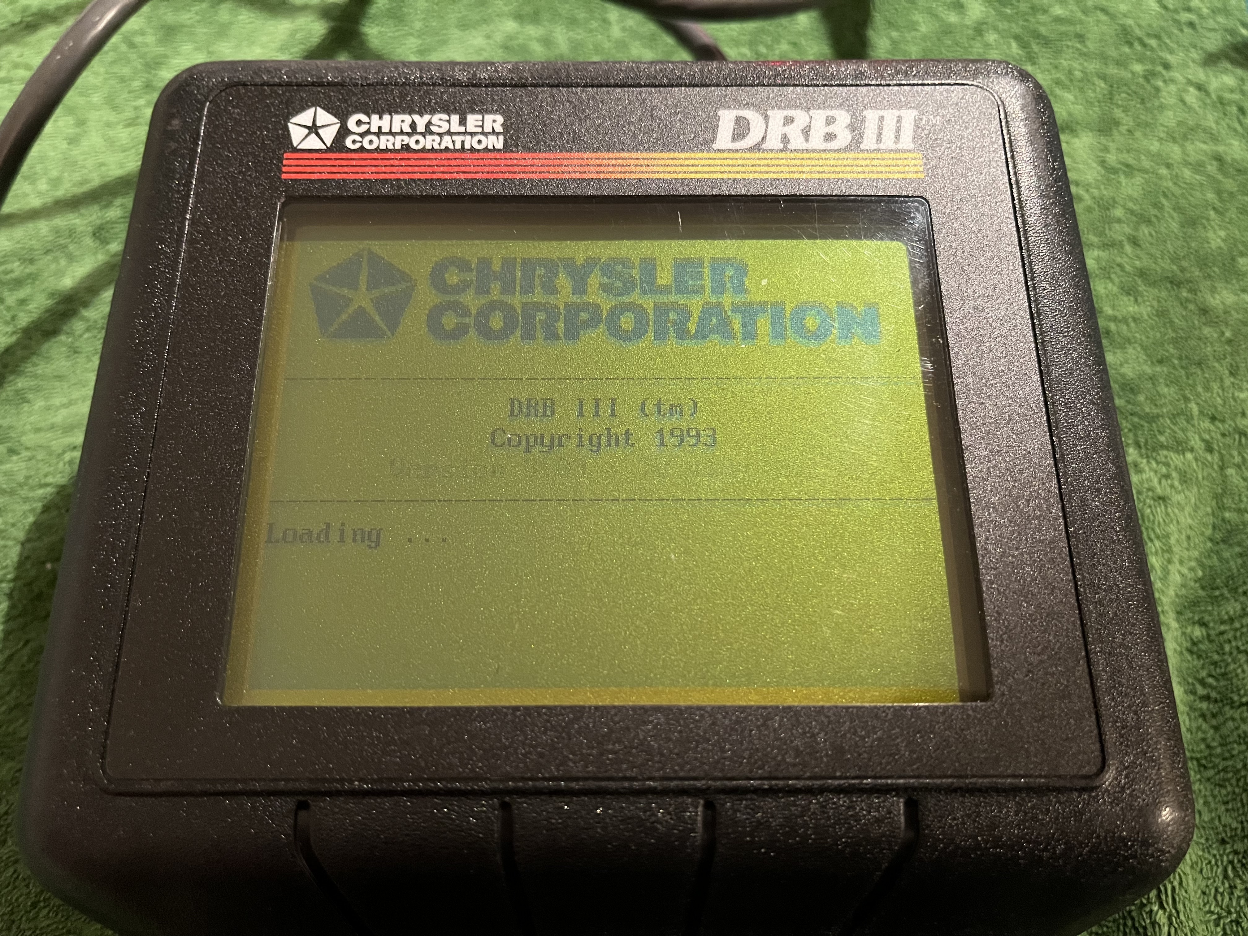
Booting up the DRB III.
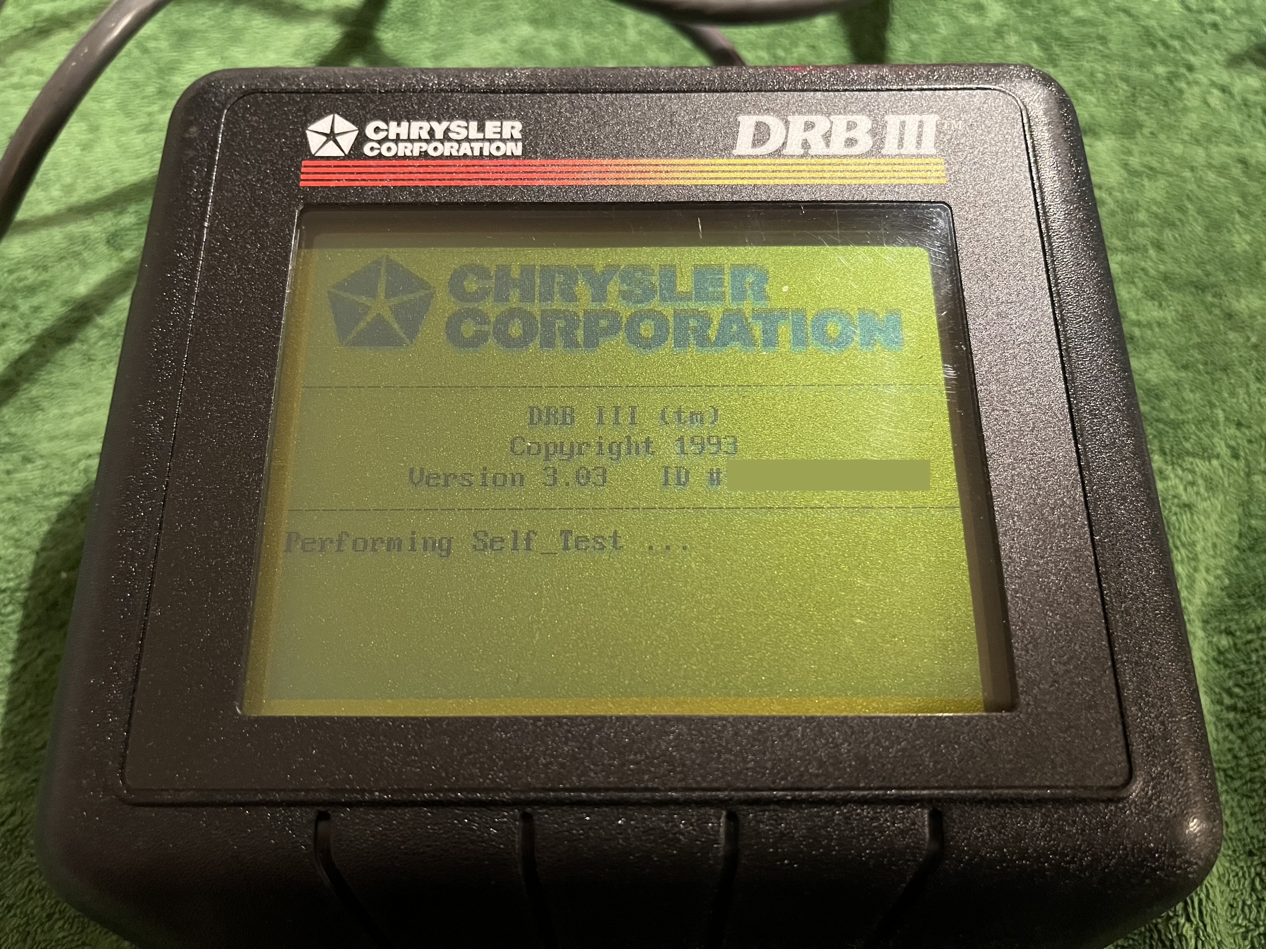
Booting up it performs a selfcheck and shows the (here censored) serialnumber of the device.
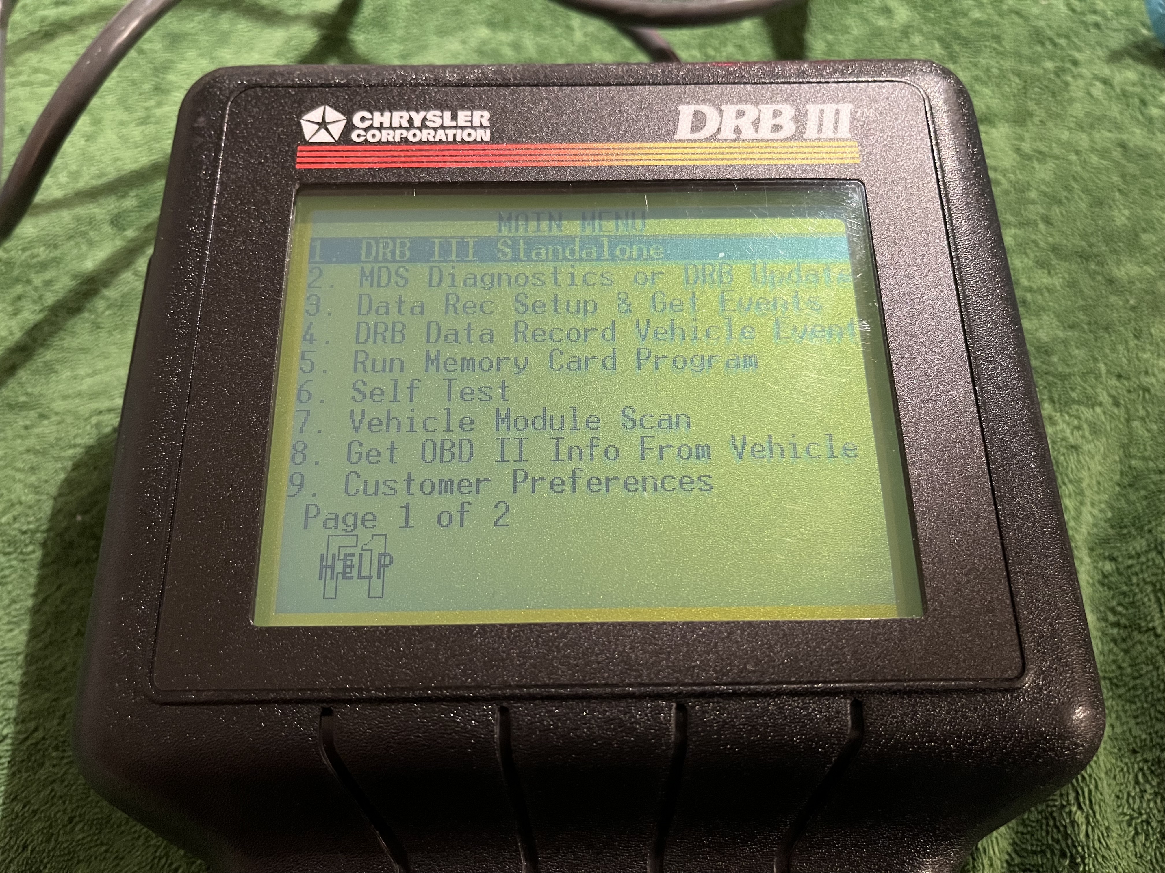
Unlike the DRB II, the DRB III can operate without a cardridge inserted. This is the main menue.
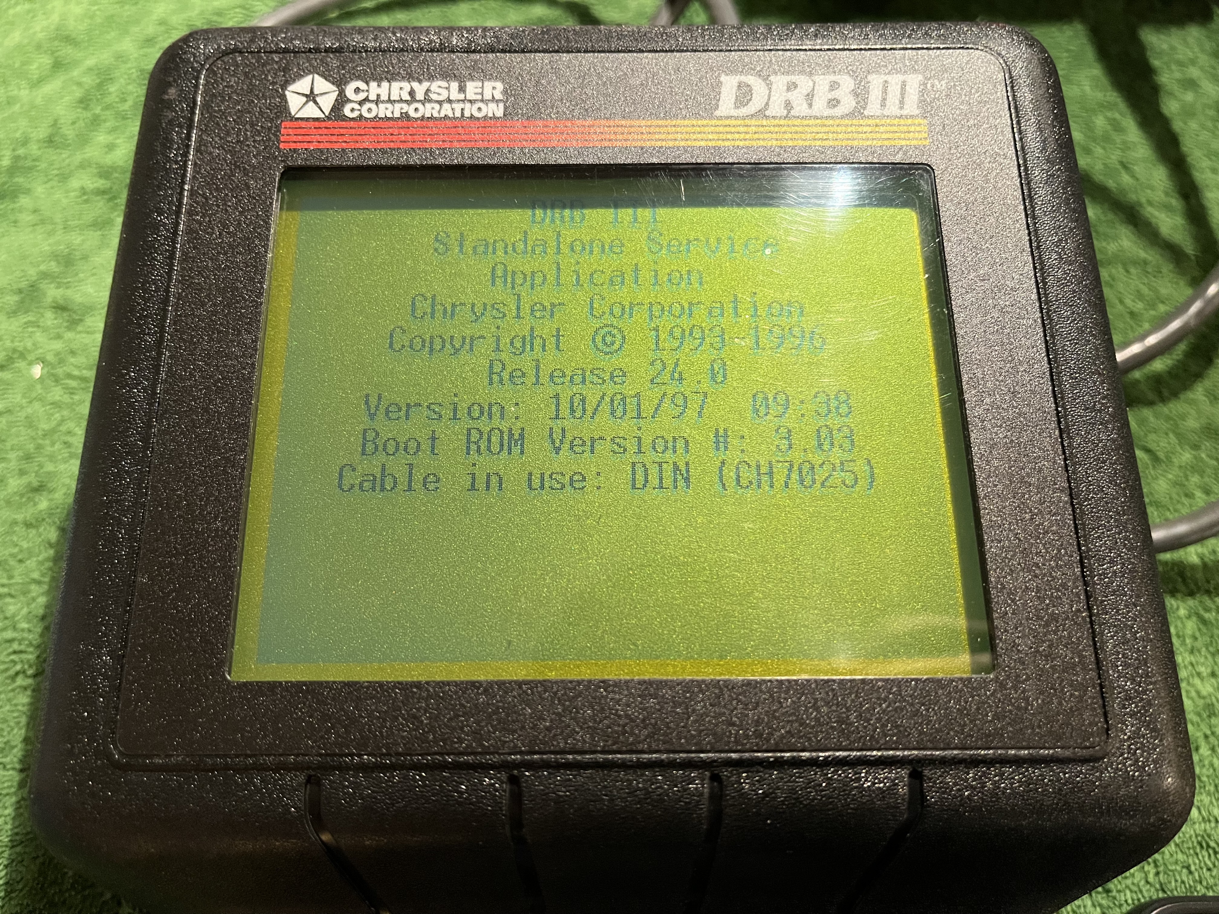
Starting the standalone mode, the DRB presents some information regarding the software. Also note the recognized cable (CH7025). The DRB III knows what cable is attached to it.
The PEP module is not meant to be removed after a certain software version and has to stay attached. This makes it seated quite well in the module bay, after long time of attachment. Using plastic tools it can be removed without harming the precious housing.
The top part is a separate housing element.
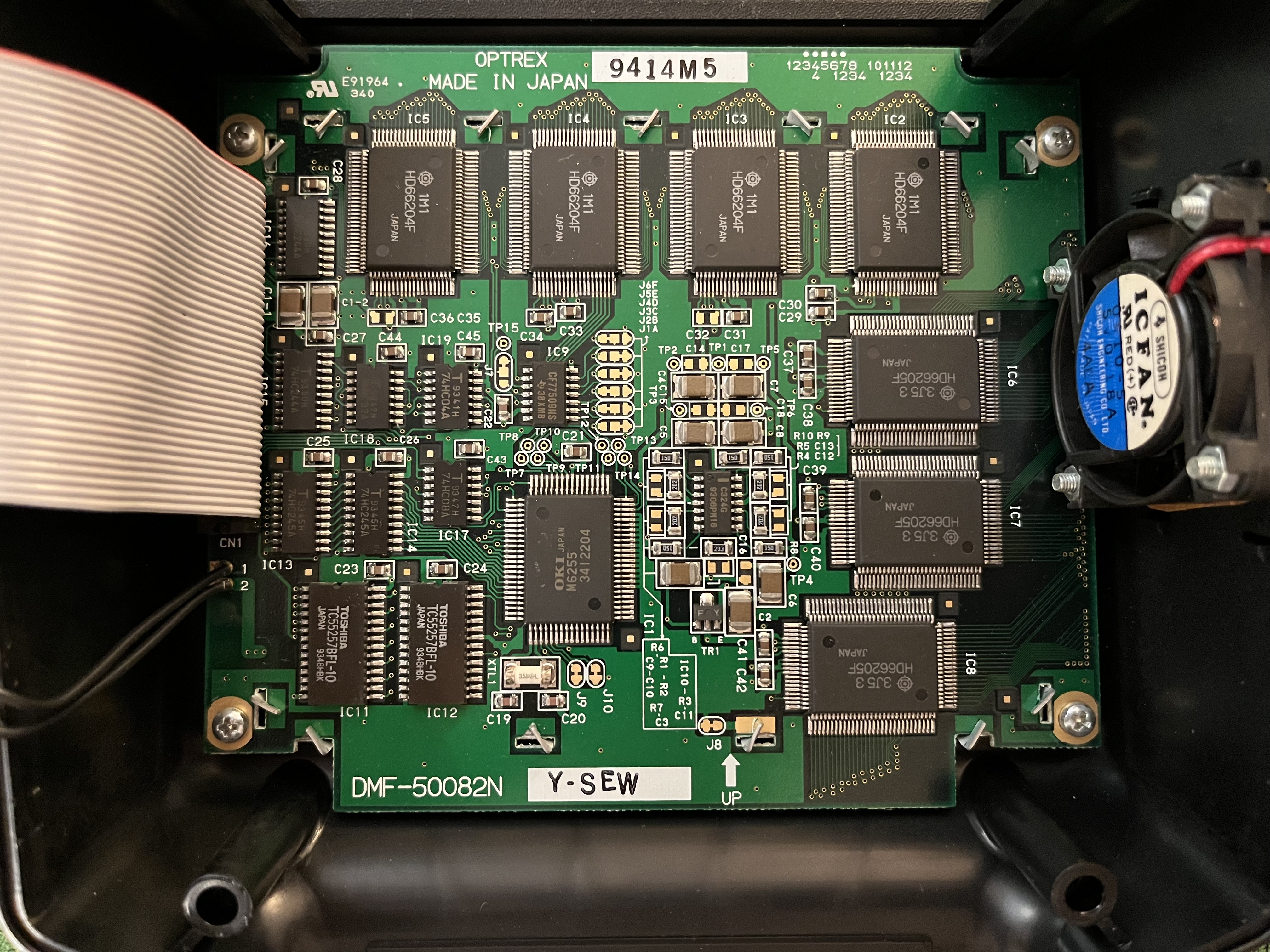
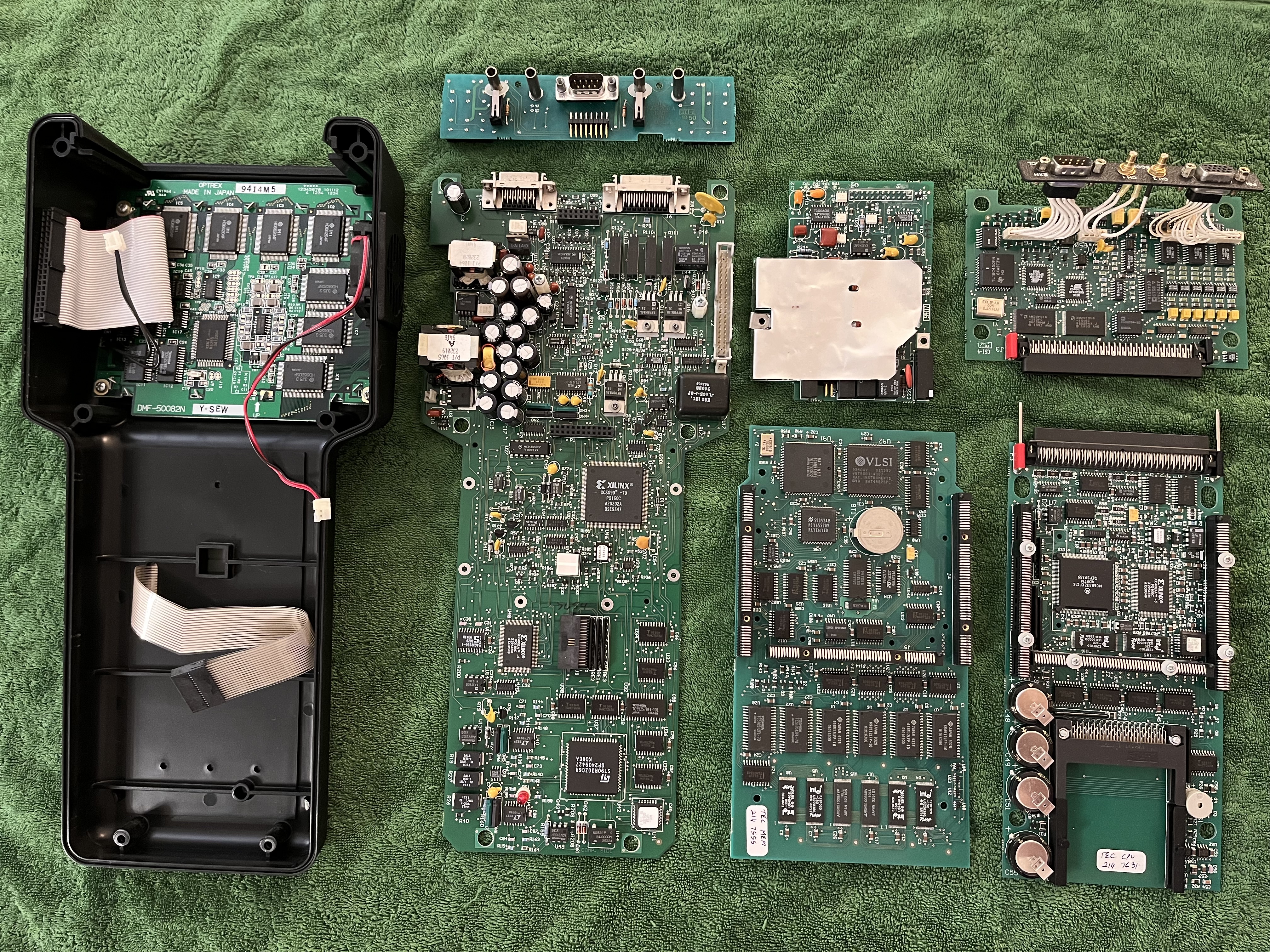
The display unit is made by Optrex, the PCB reads DMF-50082N. The PCB holds seven HD66204F chips.
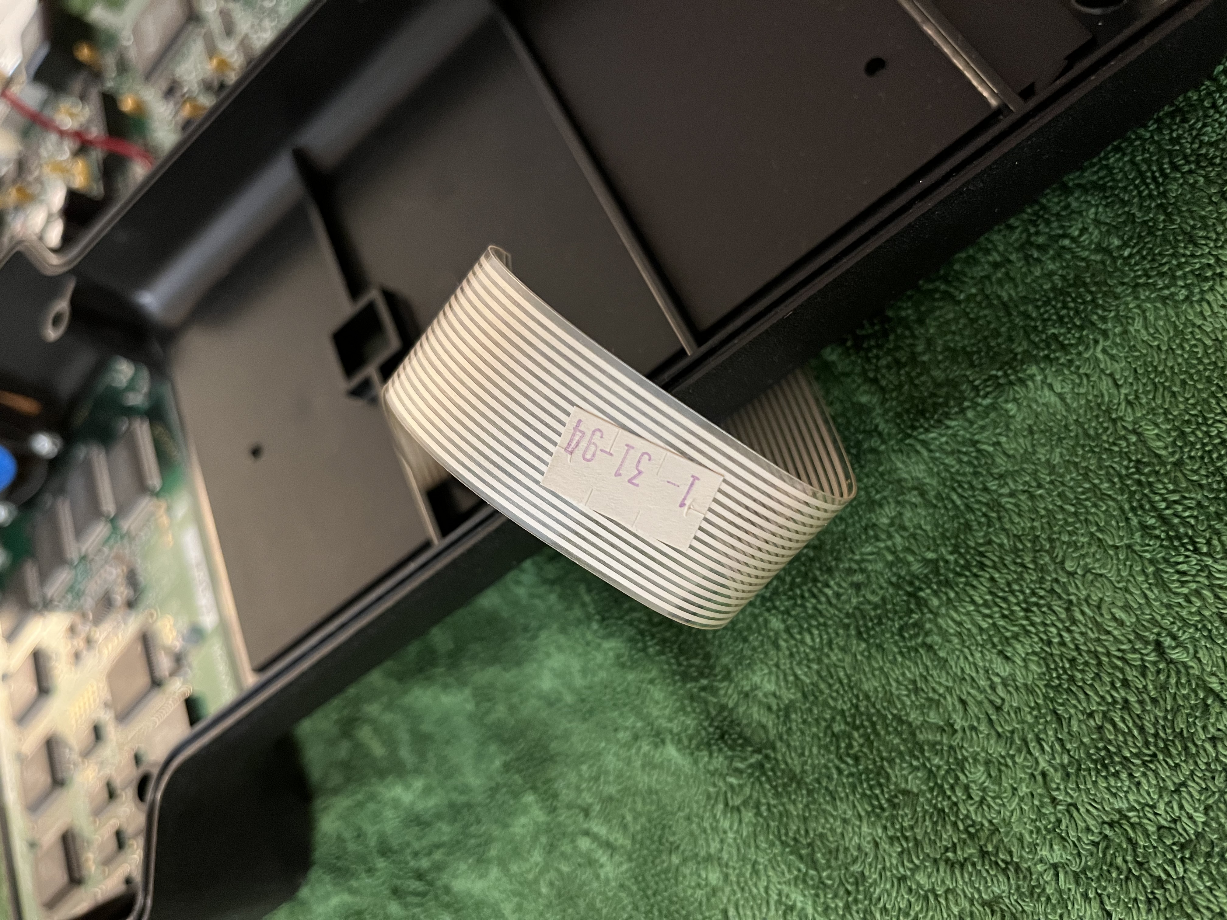
The keyboard flexcable once again gives us a good hint for when the device was built. In this case January 31 1994.
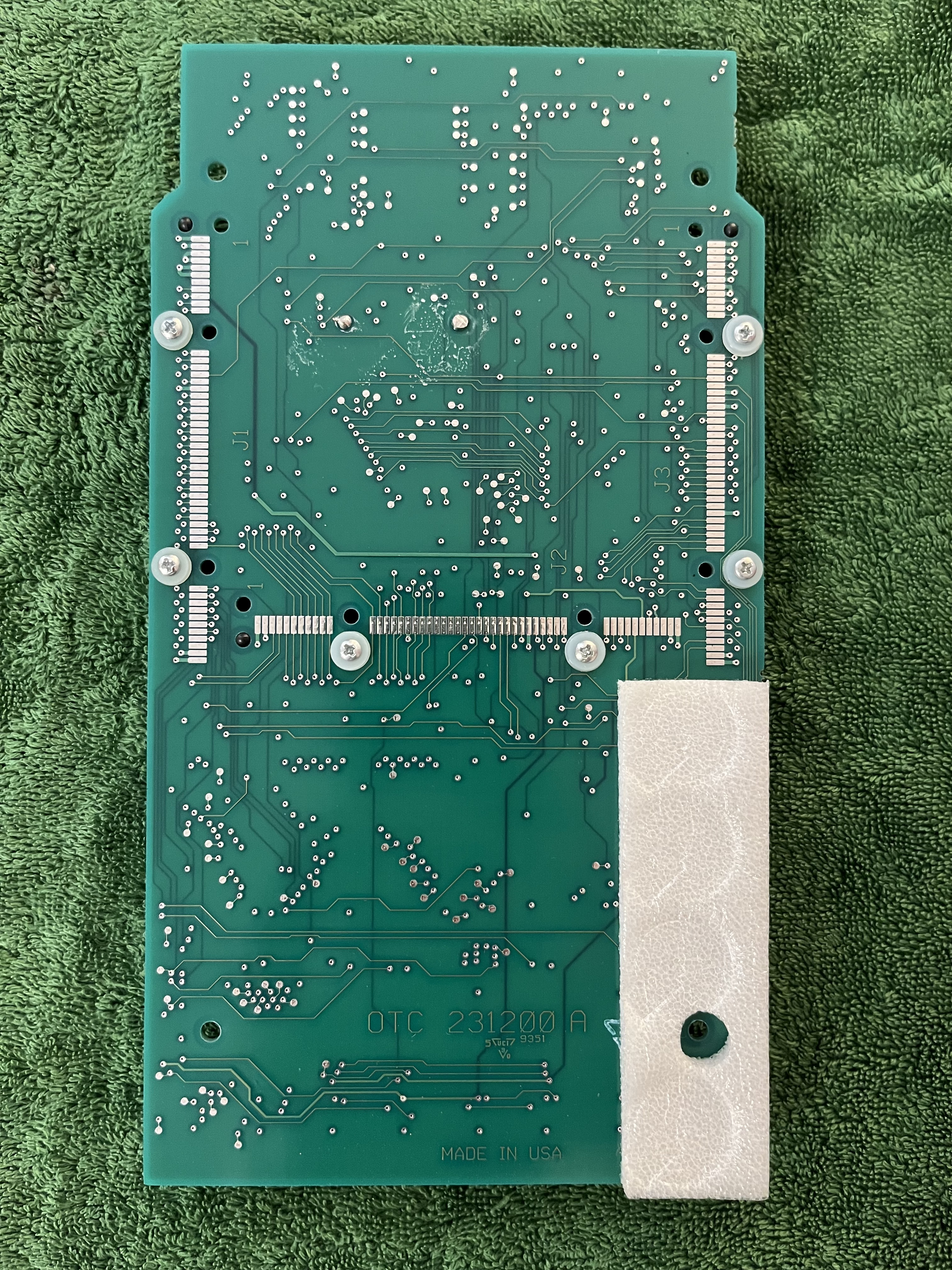
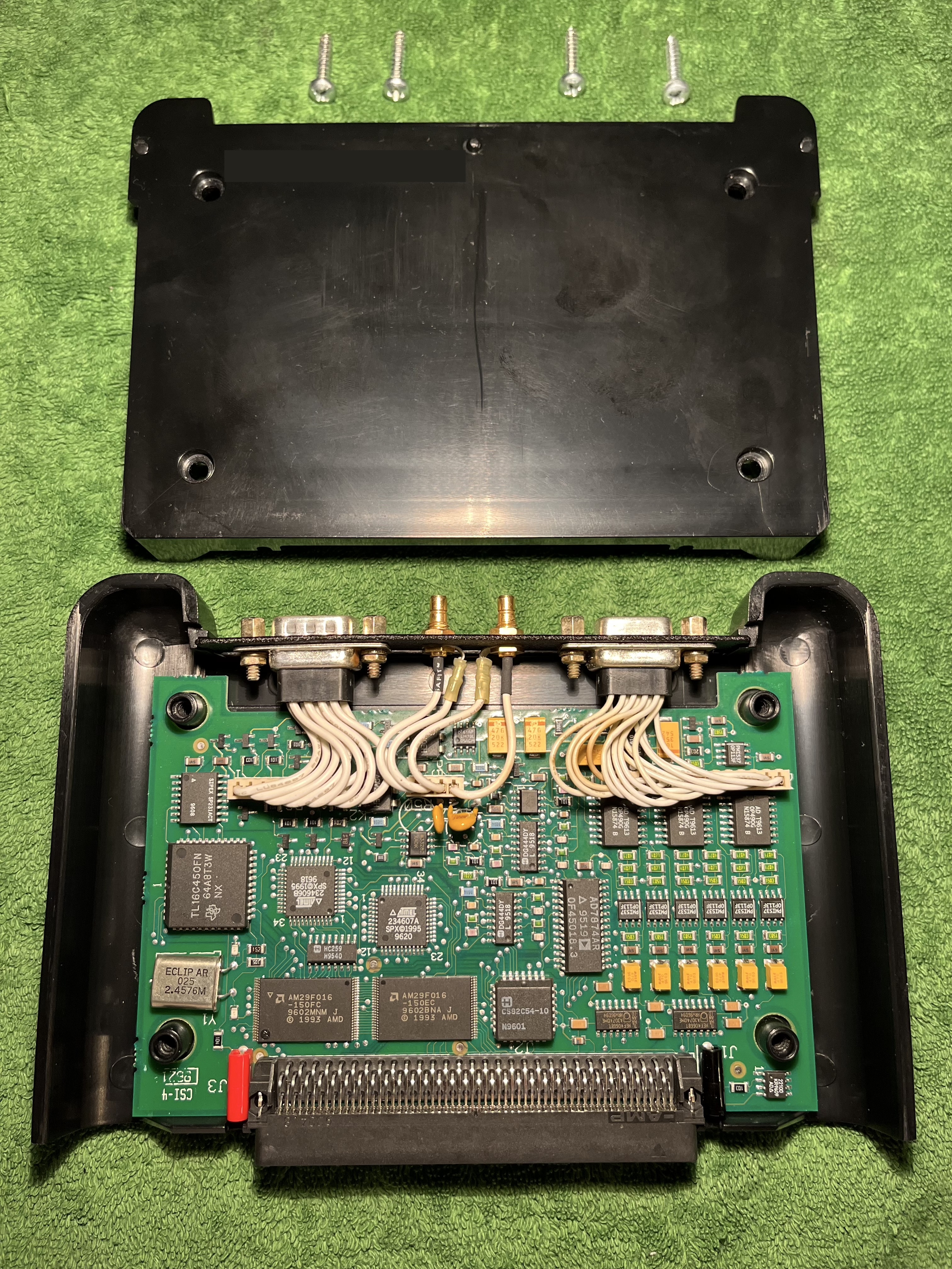
This is the second PCB, after removing the first board.
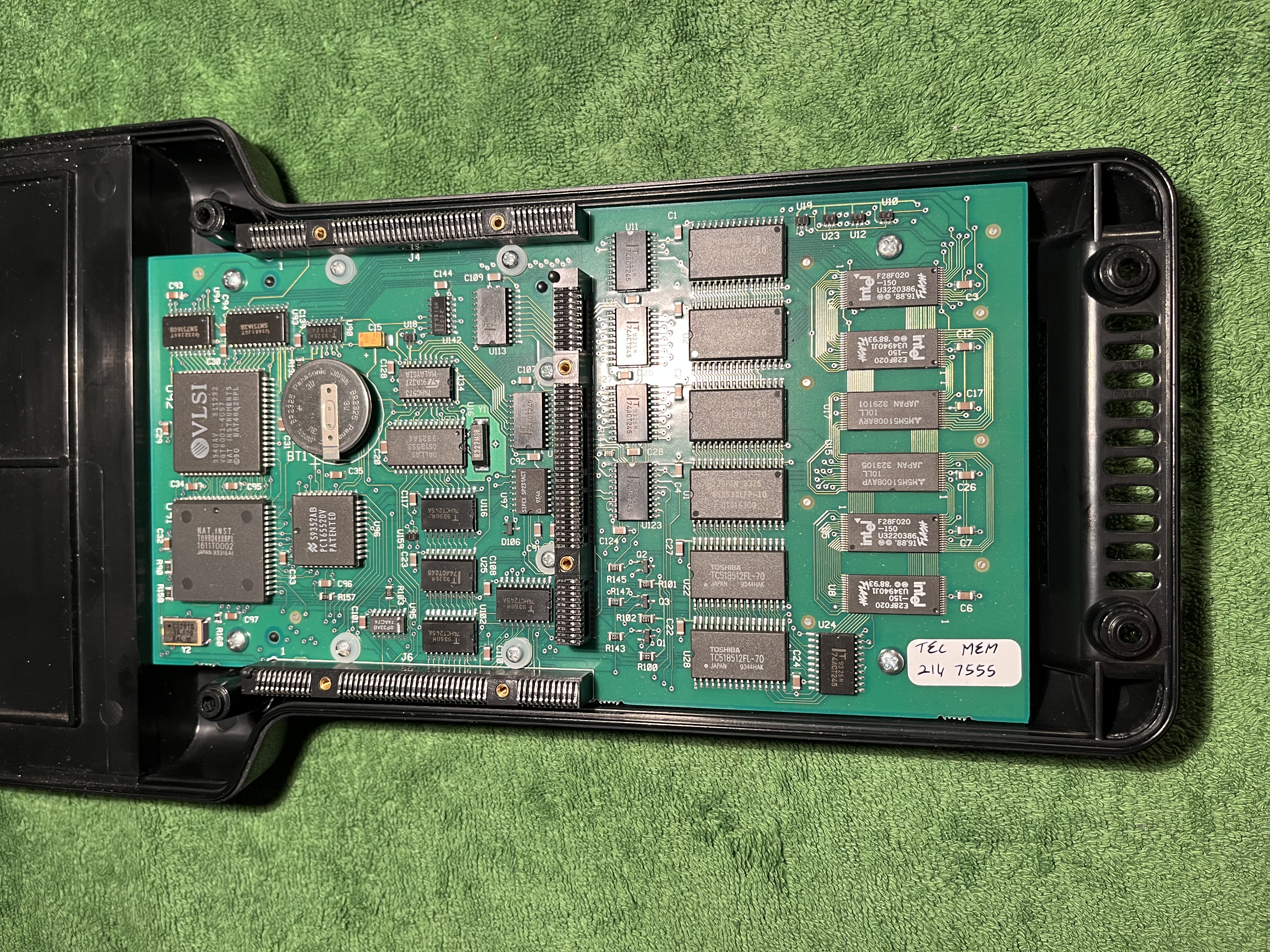
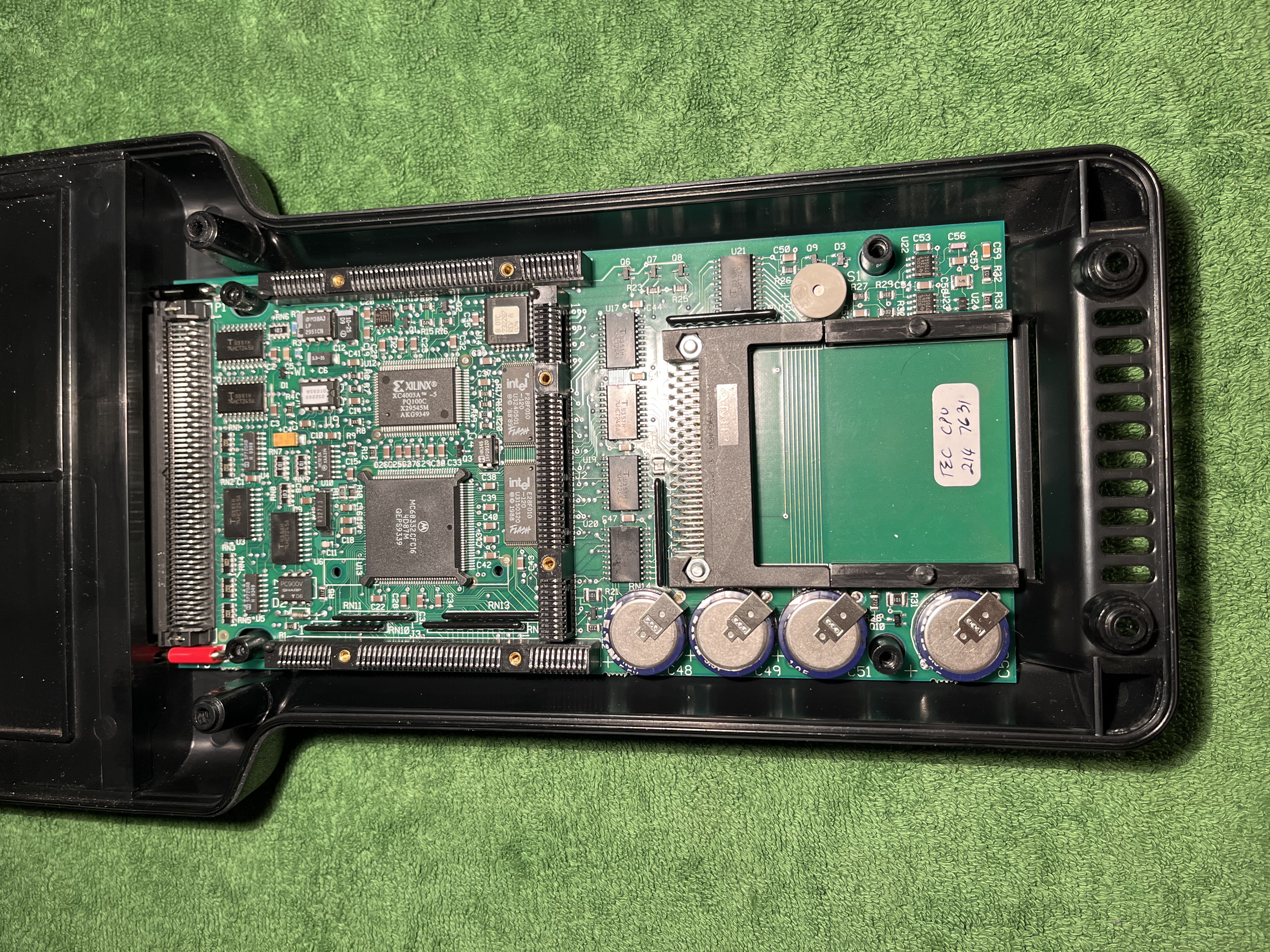
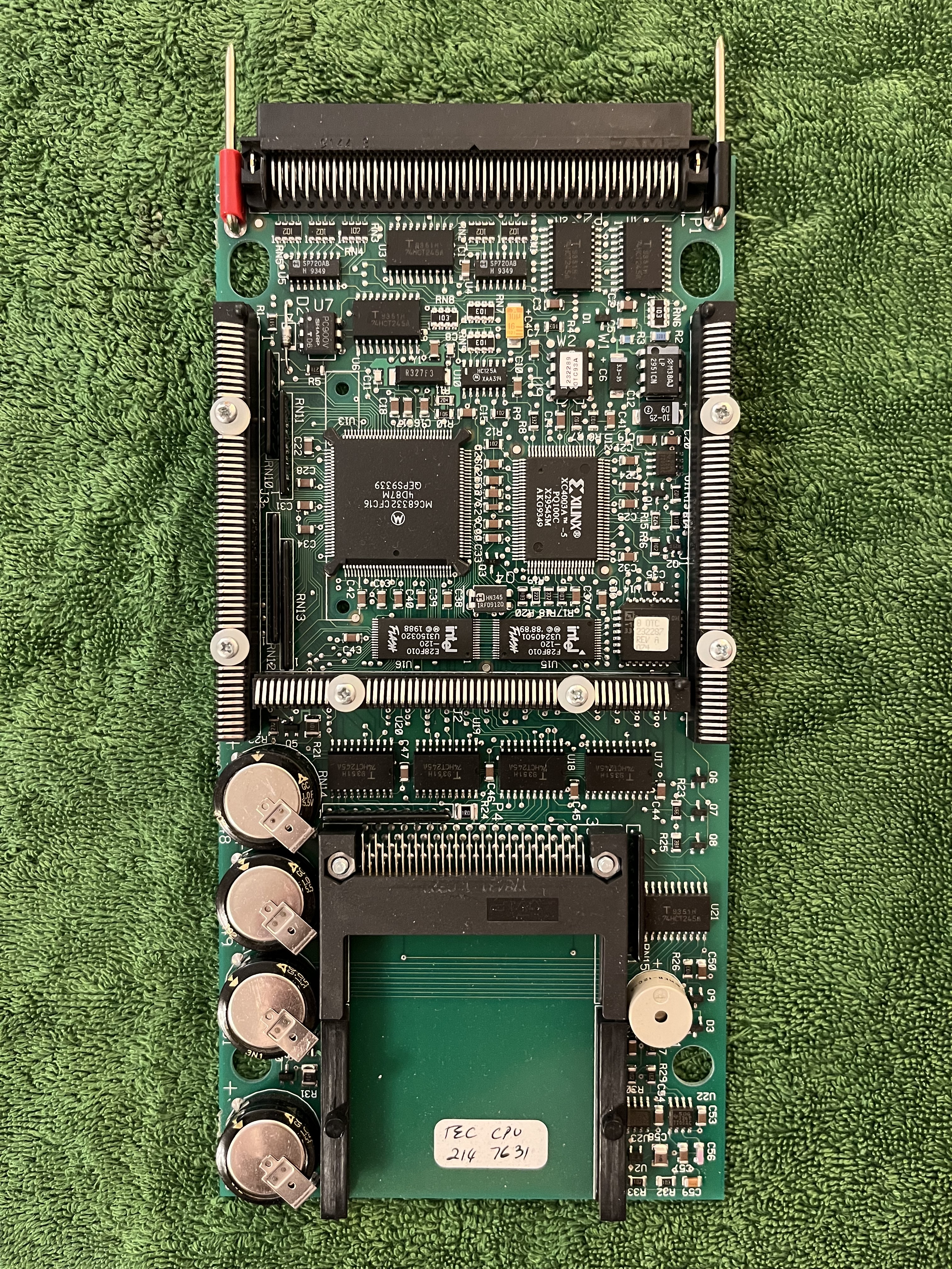
This is the third and last big PCB. It holds an processor from Motorola, MC68332 CFC16. A quick search suggests its a 32 bit CPU from the Motorola 6800 family. The PCBs are stacked ontop of each other, connecting via the touching pins and beeing screwed together.
Alltogether the DRB III looks like an absolute beast of technology, consisting of not less than 7 PCBs. Including the PEP module.
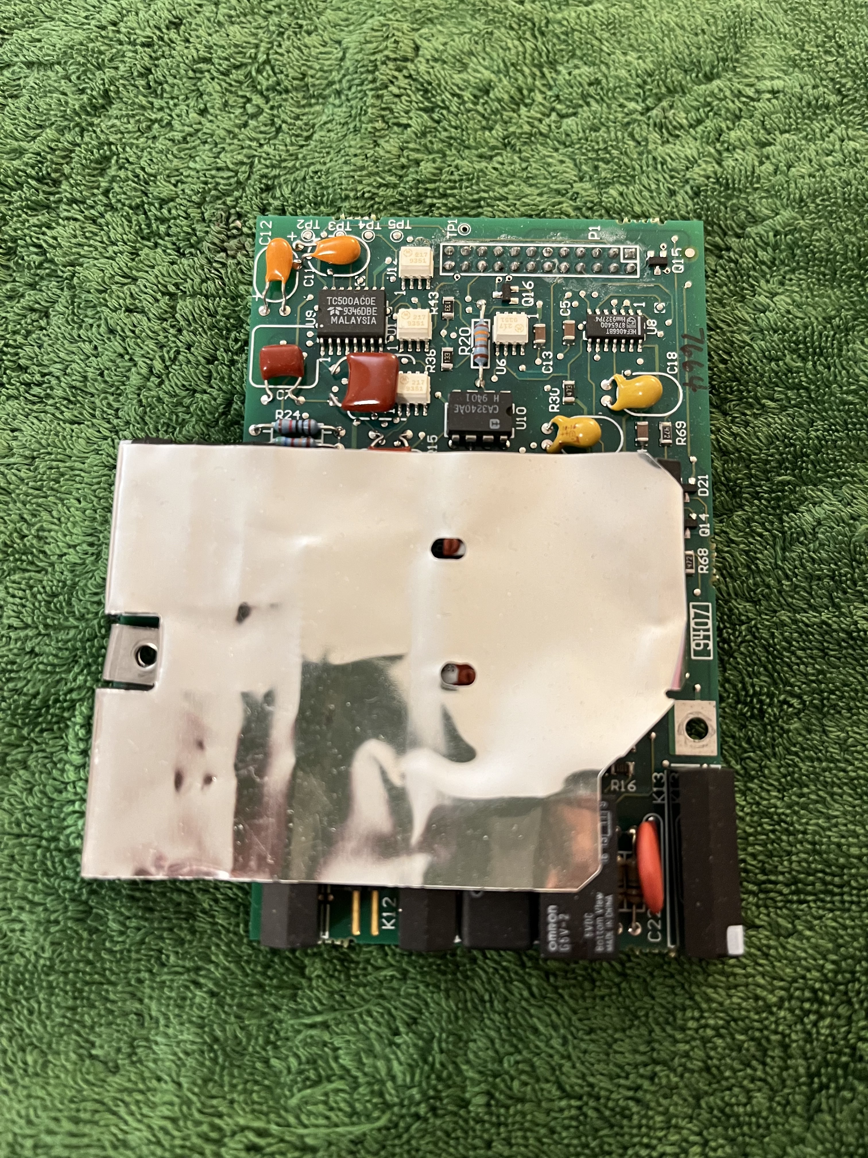
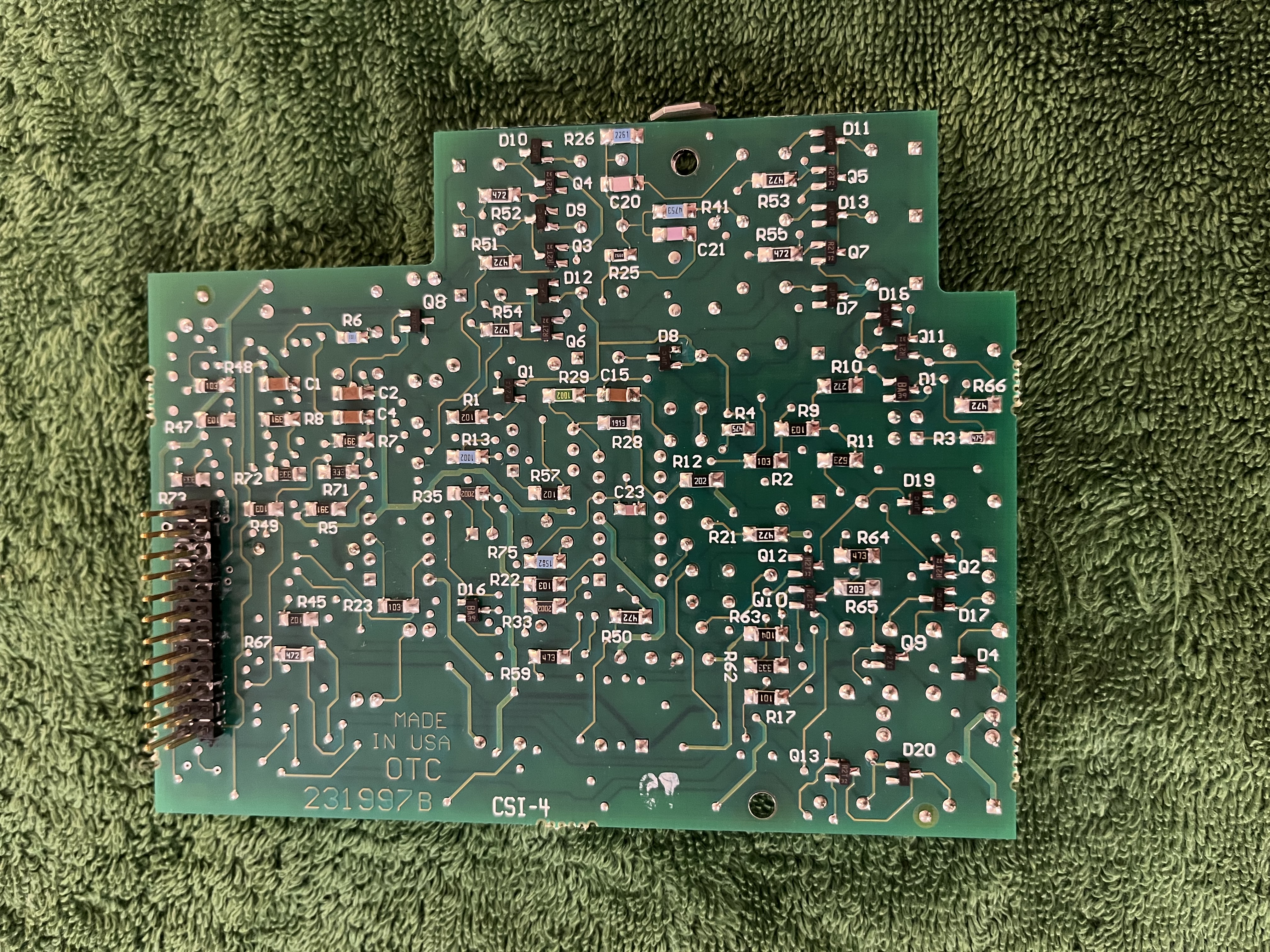
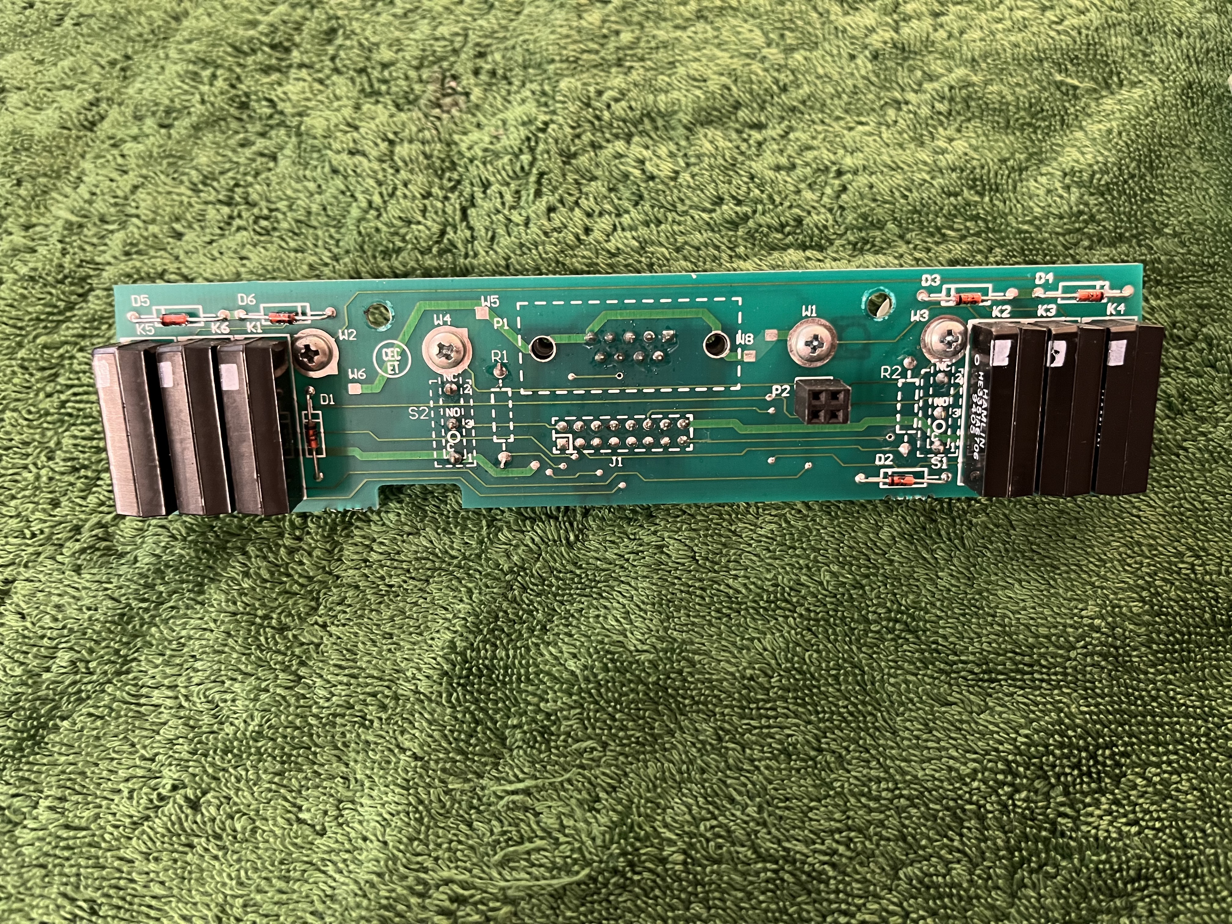
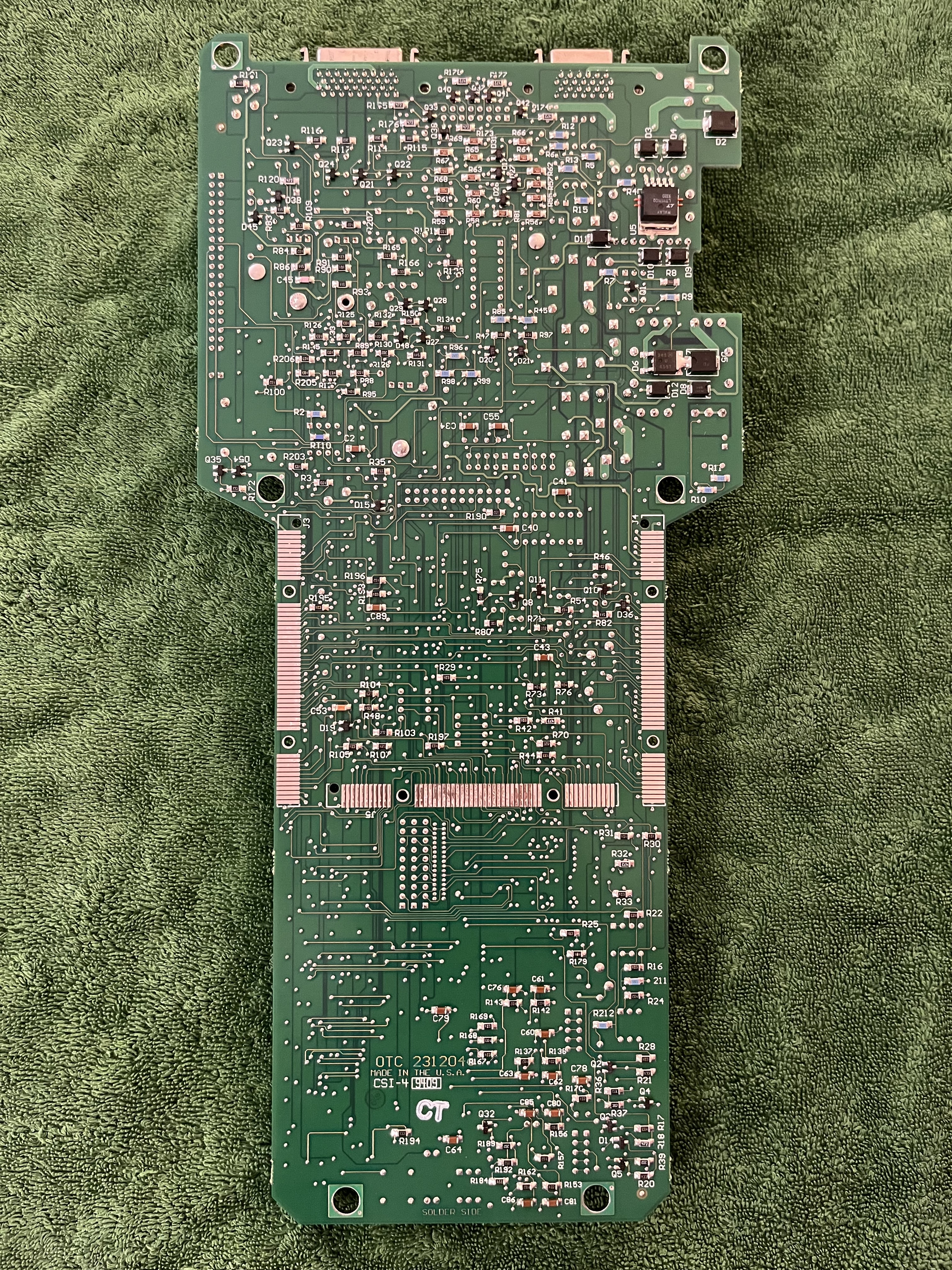
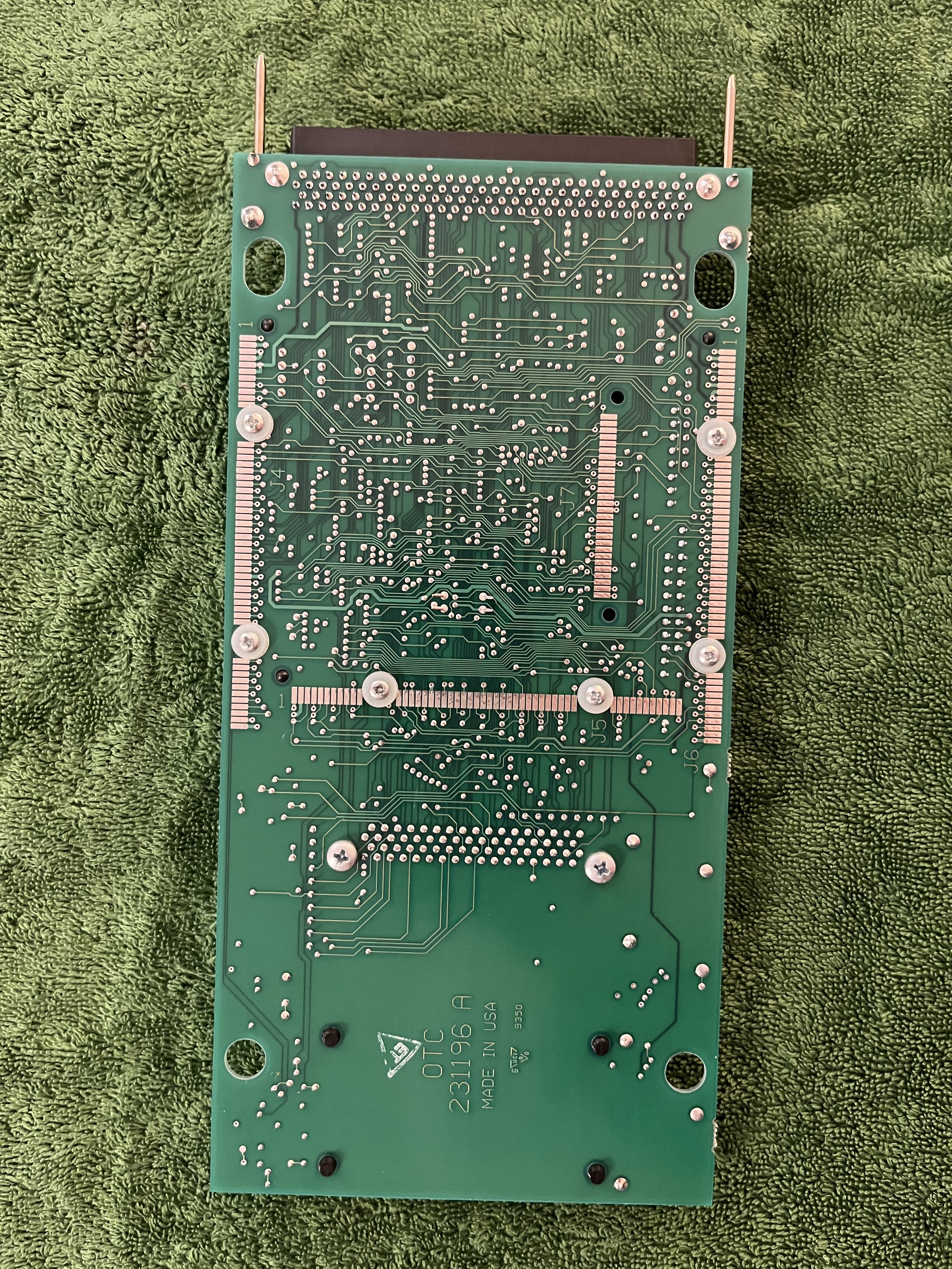
No idea what this PCB does. However it is build by OTC in the USA, like all the other PCBs.
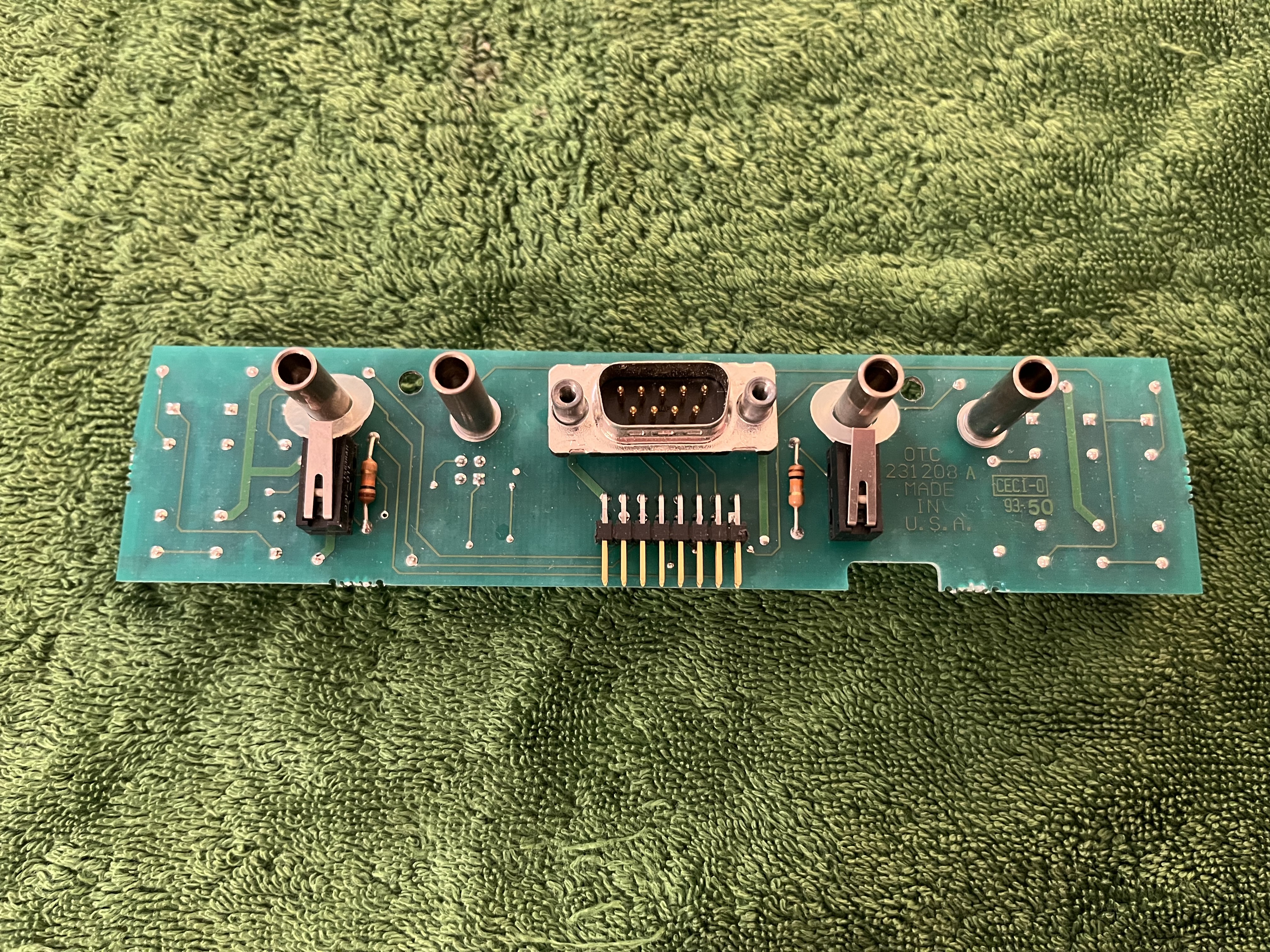
This is the PCB for the RS232 connector and leads.
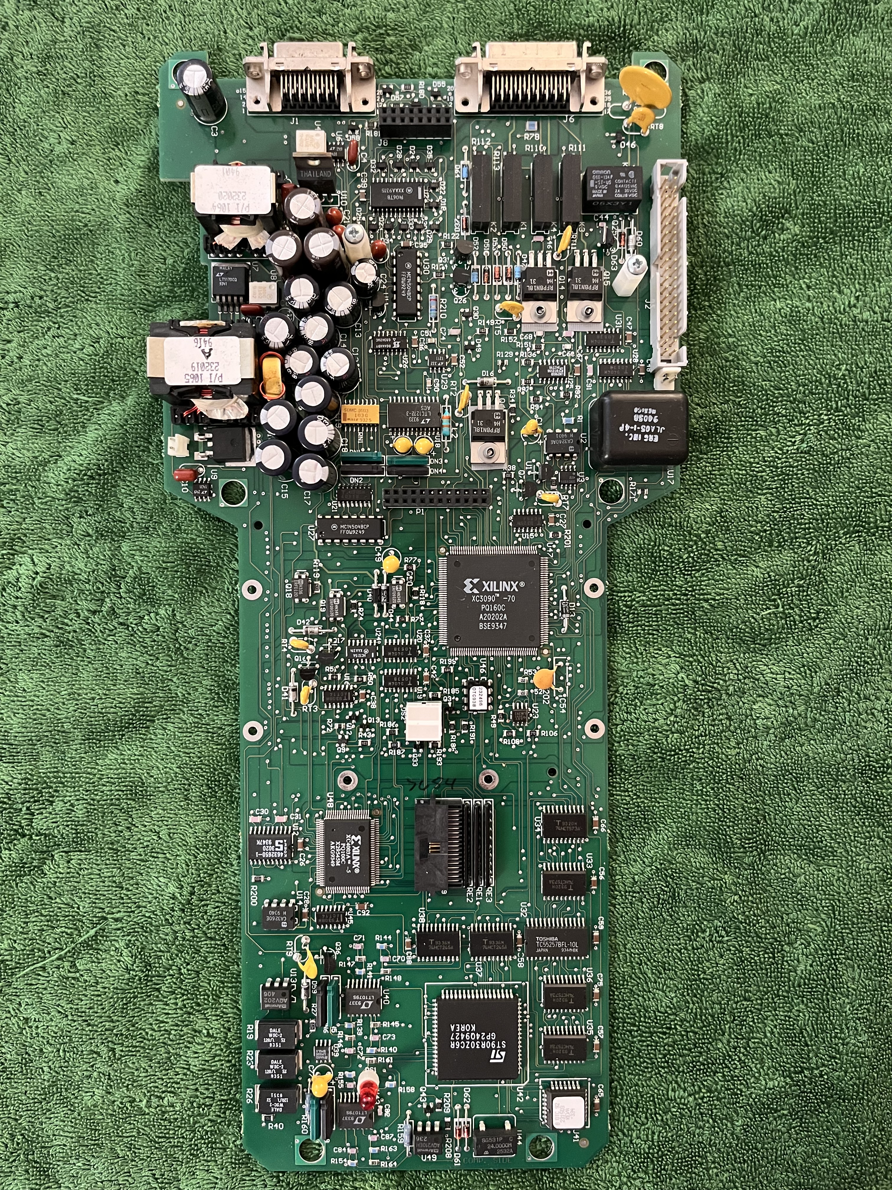
This is the first PCB in the stacking-order. Notable is the Xilinx XC3090 -70 chip. This chip seems to be an FPGA.
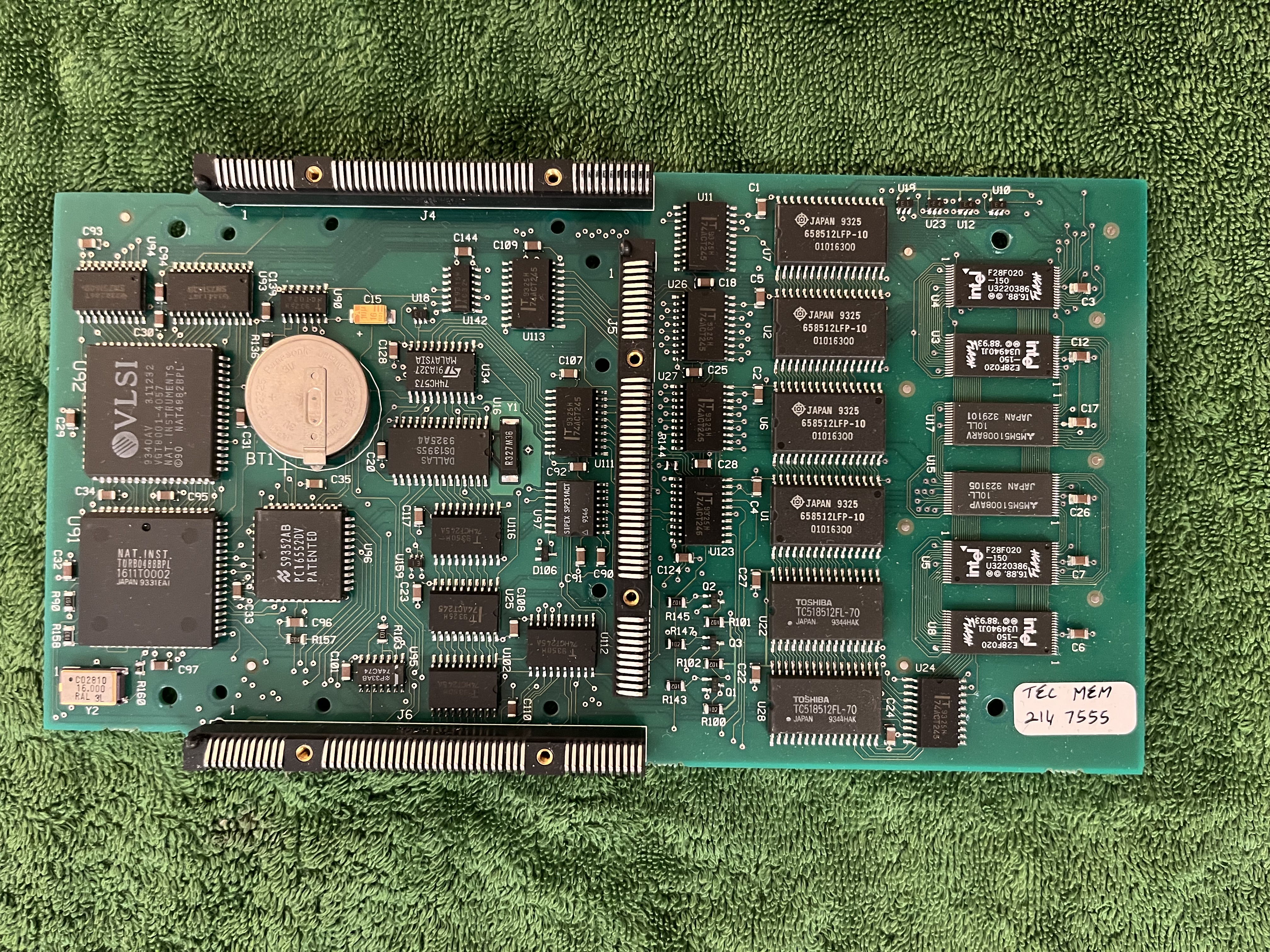
Closer look at the seconds PCB.
Closer look at the third PCB. The PEP module connects to that PCB.
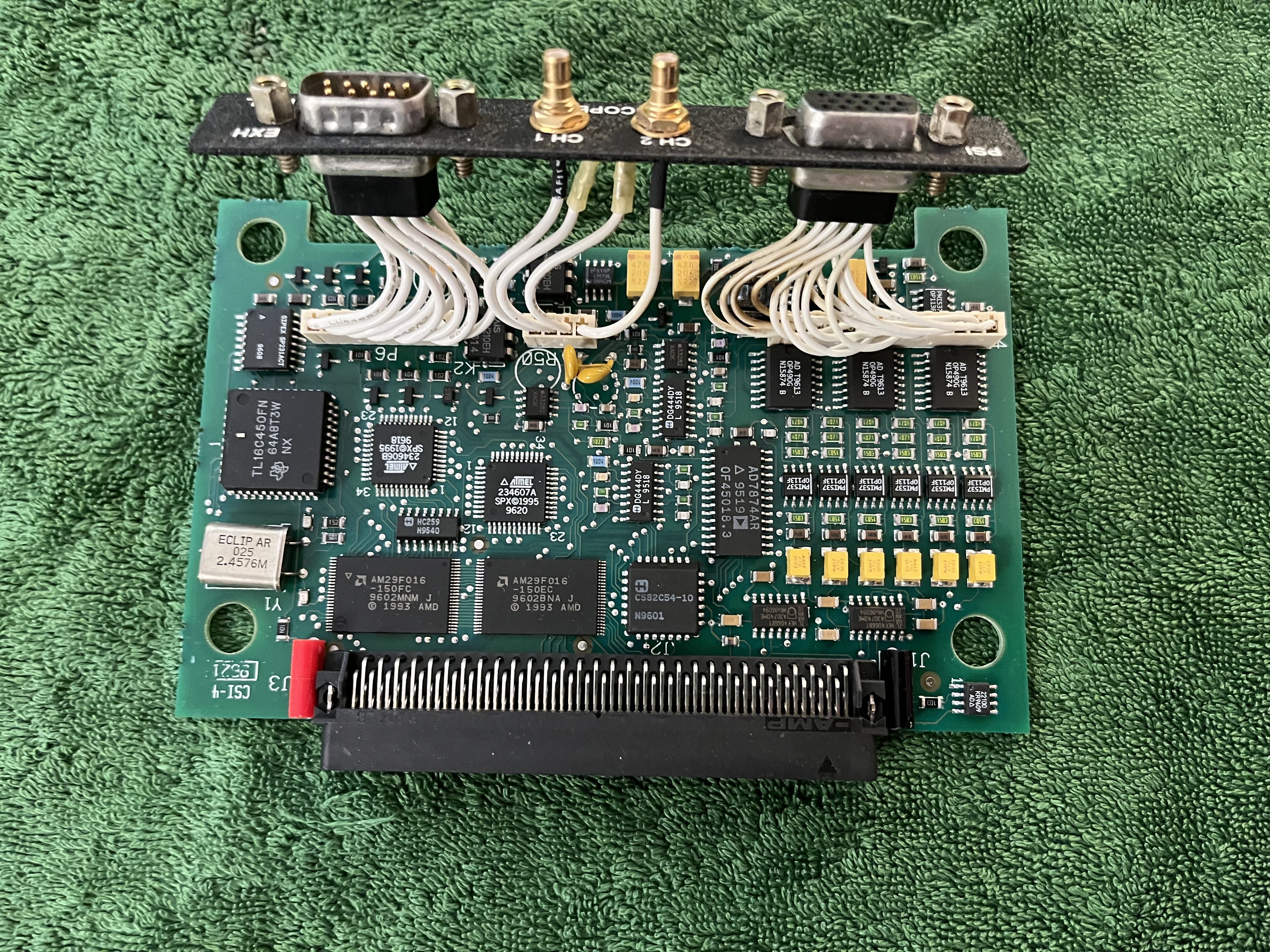
Closer look at the PEP Module, it also has its own serial number.
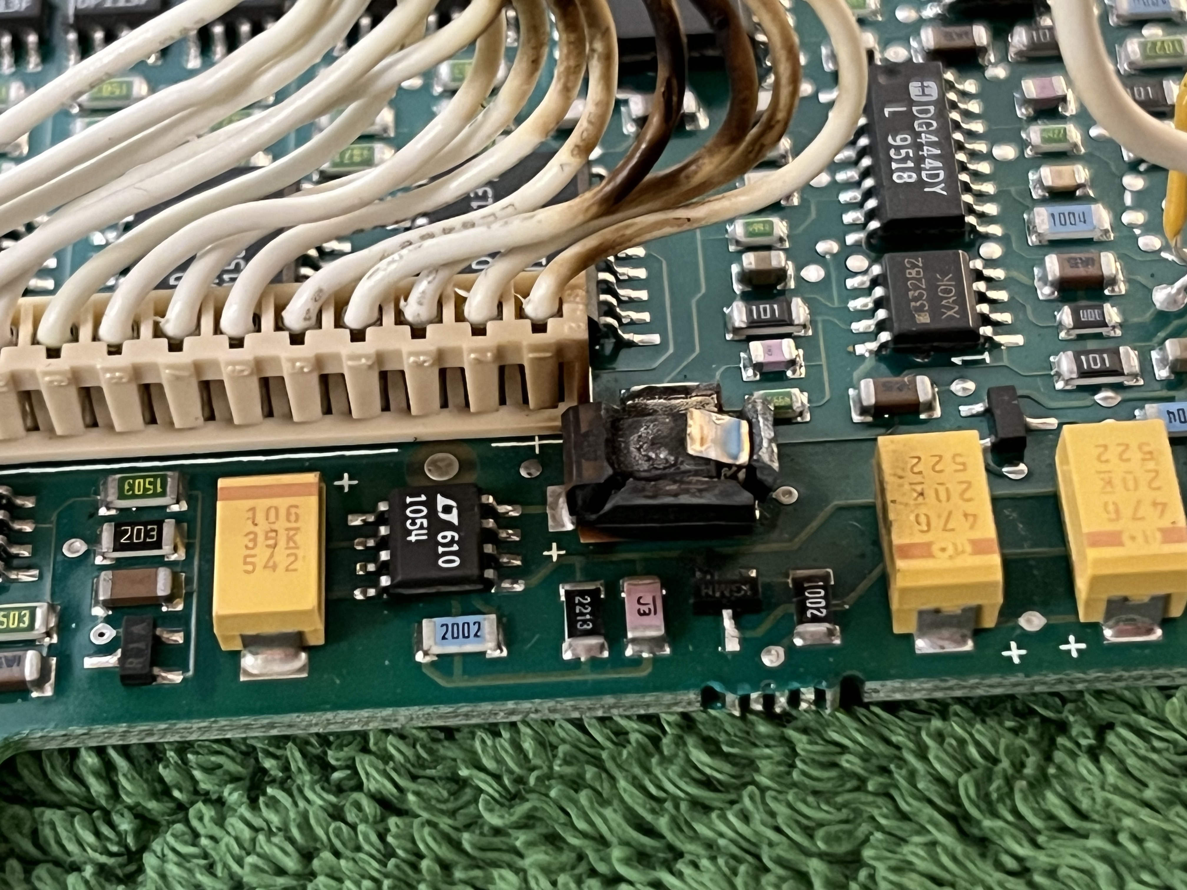
This DRB III was running on an MDS powersupply on the bench when it started to stink and release some magic smoke. Sure enough a ceramic cap decided to convert electrical power into heat (and sweat on its owners forehead). The cap had the same value as the two on the right.
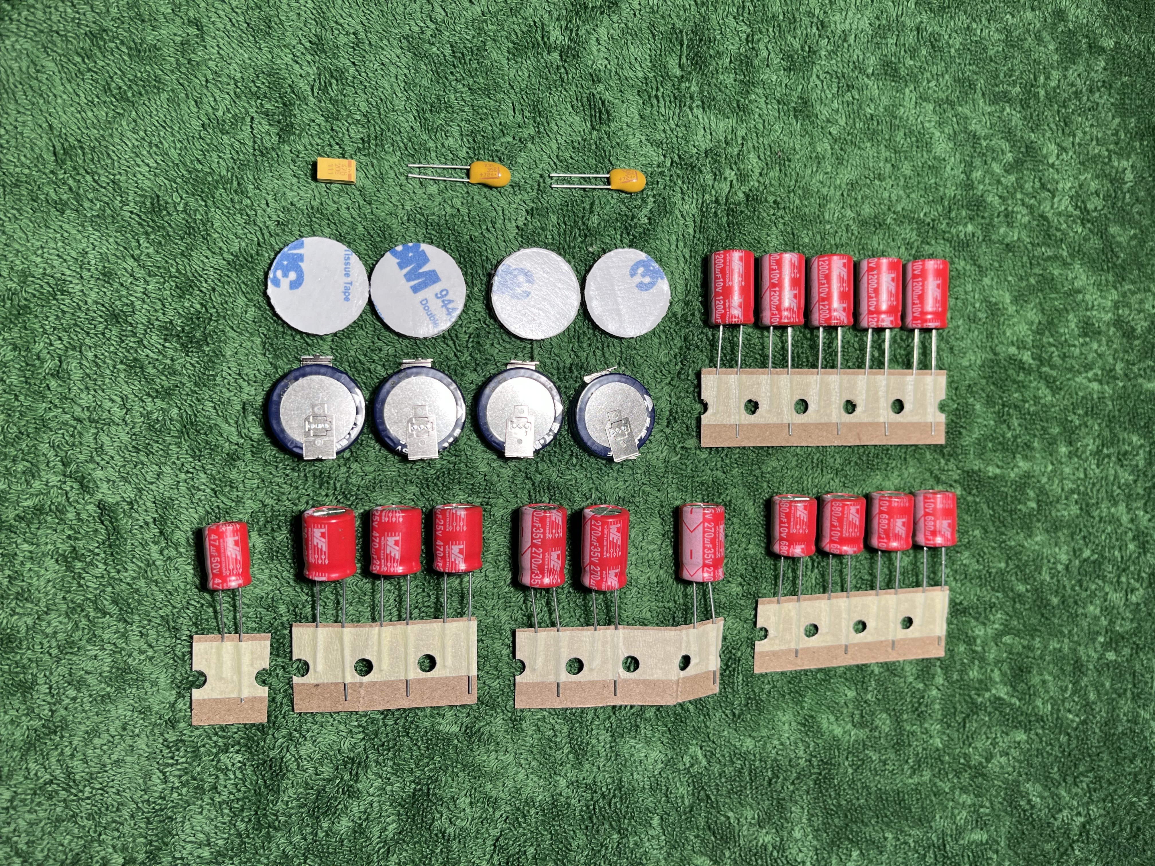
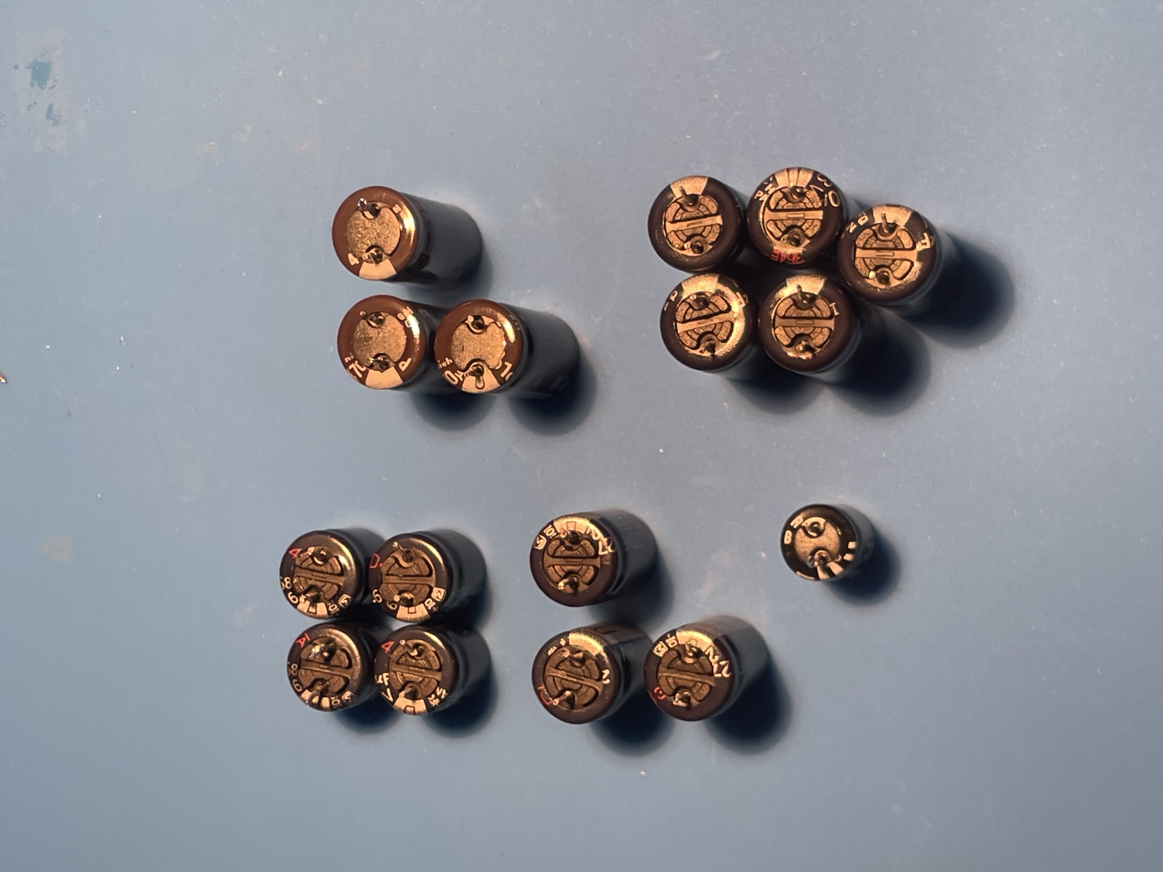
While looking for information for a way out of misery, a so called “1015 service” came along. It seems as the caps of a DRB III need to be changed after some time. Given the characteristics of caps and the age of 30 years of this specific unit it made sense to perform this service. This set of caps was bought on eBay, specifically for the DRB III.
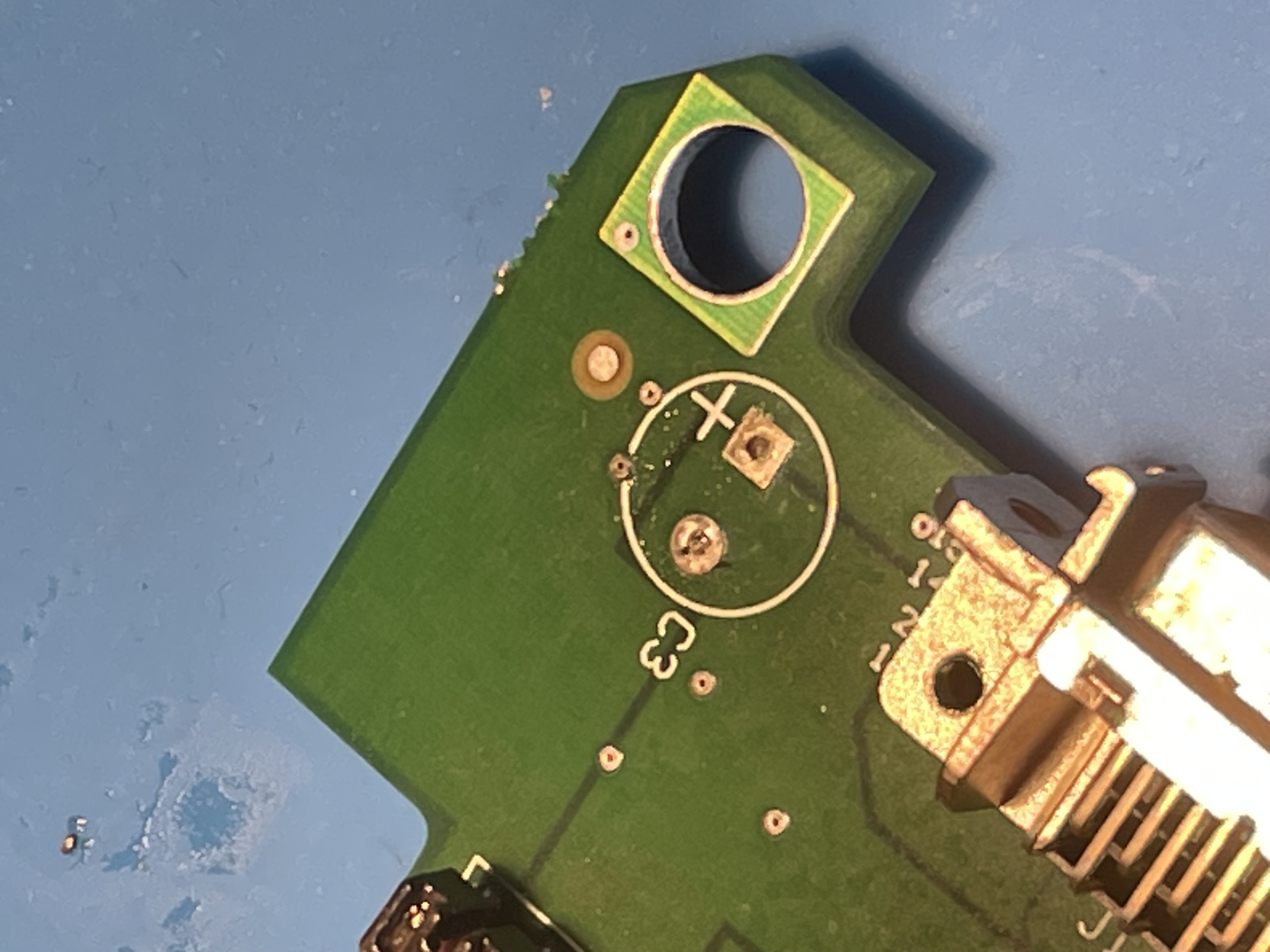
First, the ceramic cap is exchanged.
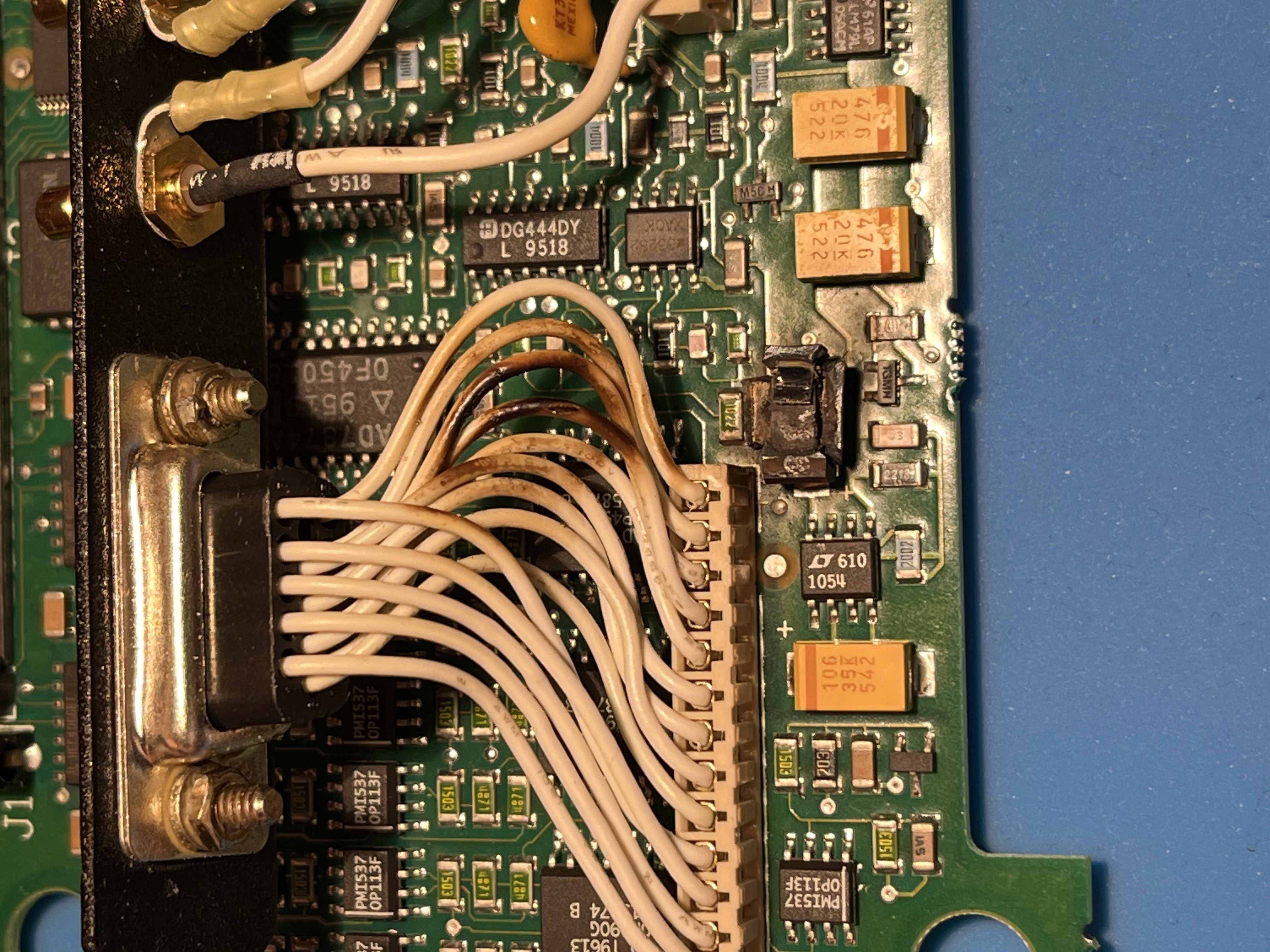
It seems liek the cap only damaged itself.
All fixed up and ready to go.
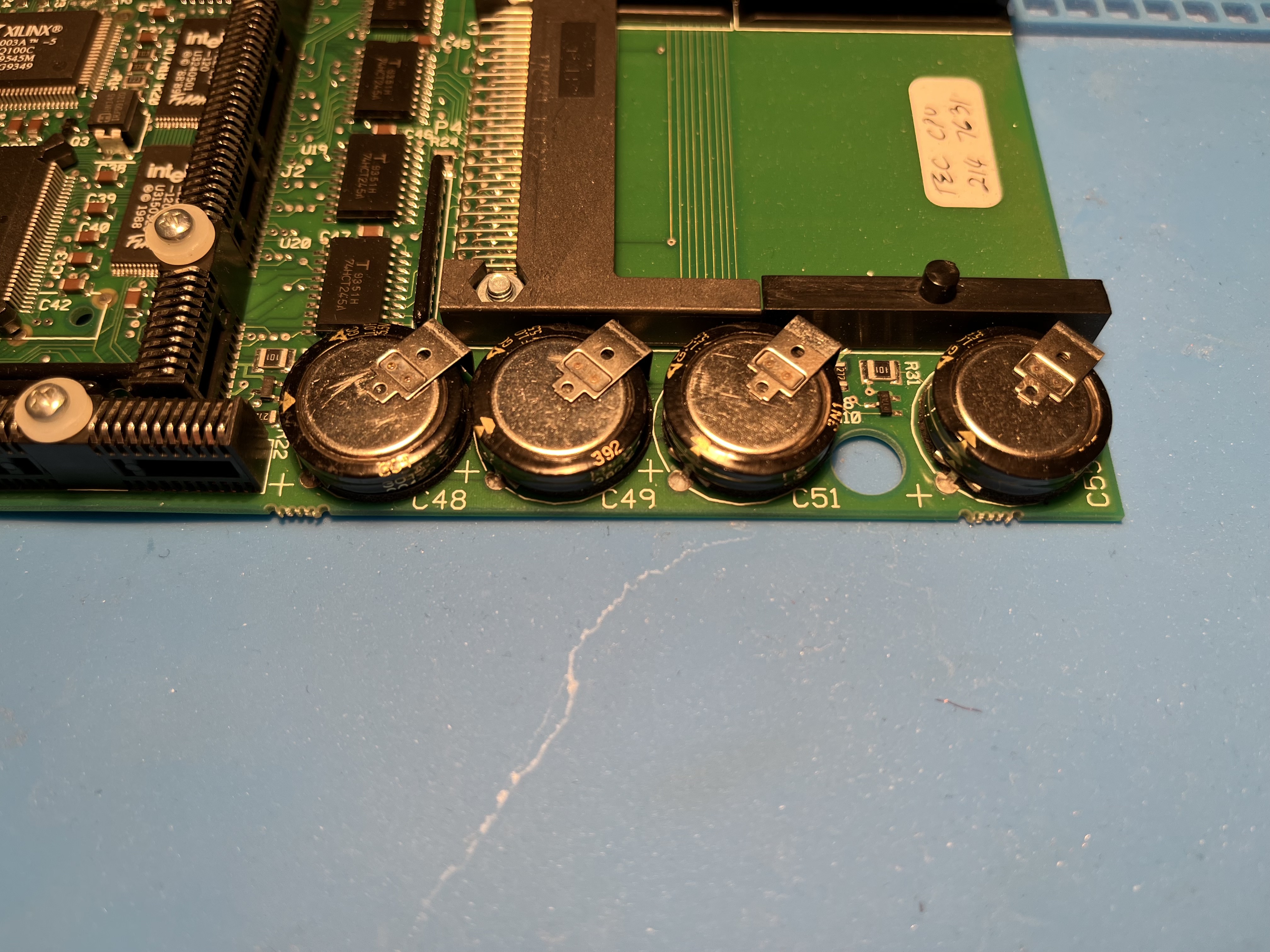
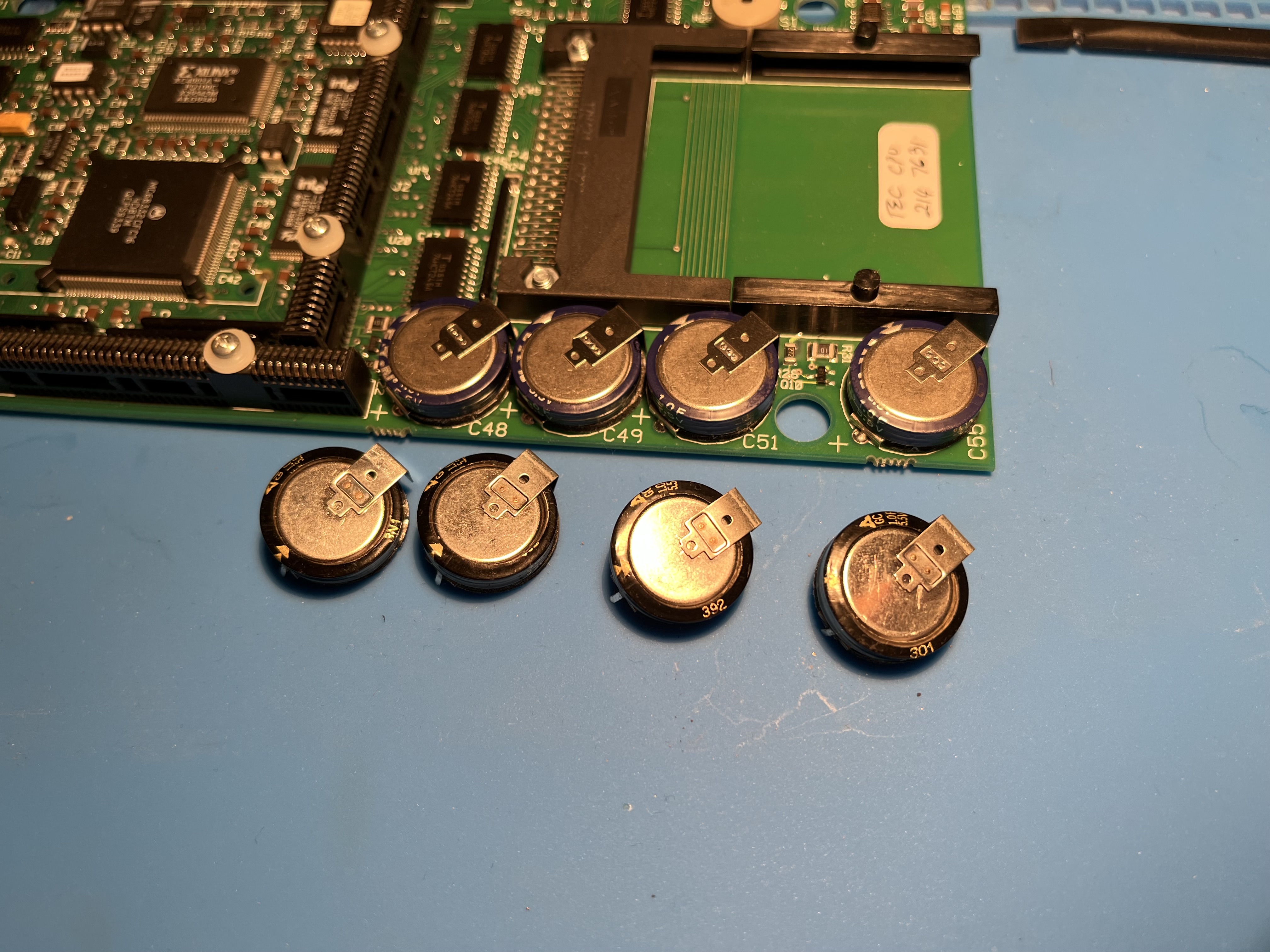
Next are the four supercapacitors on the third PCB.
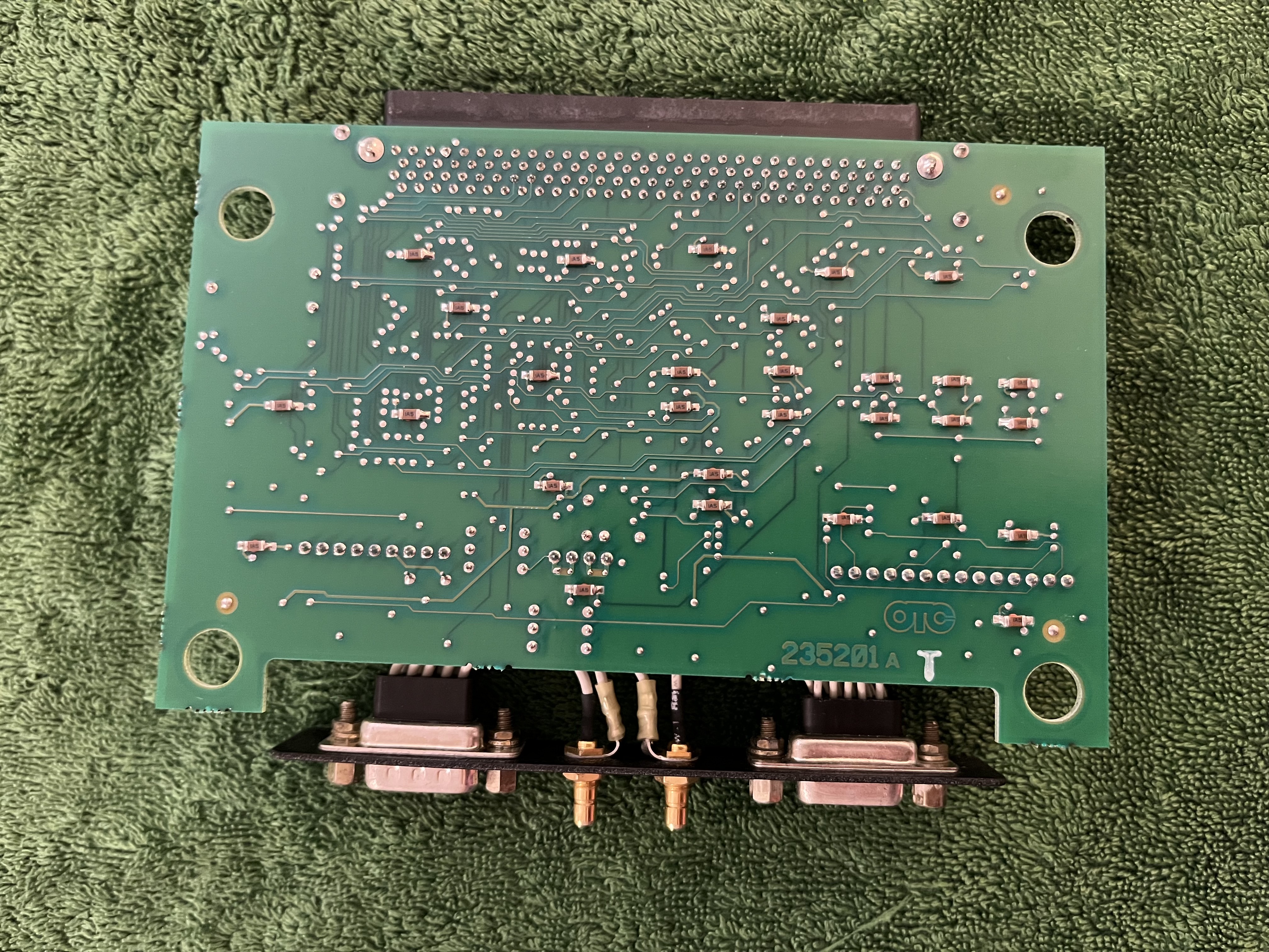
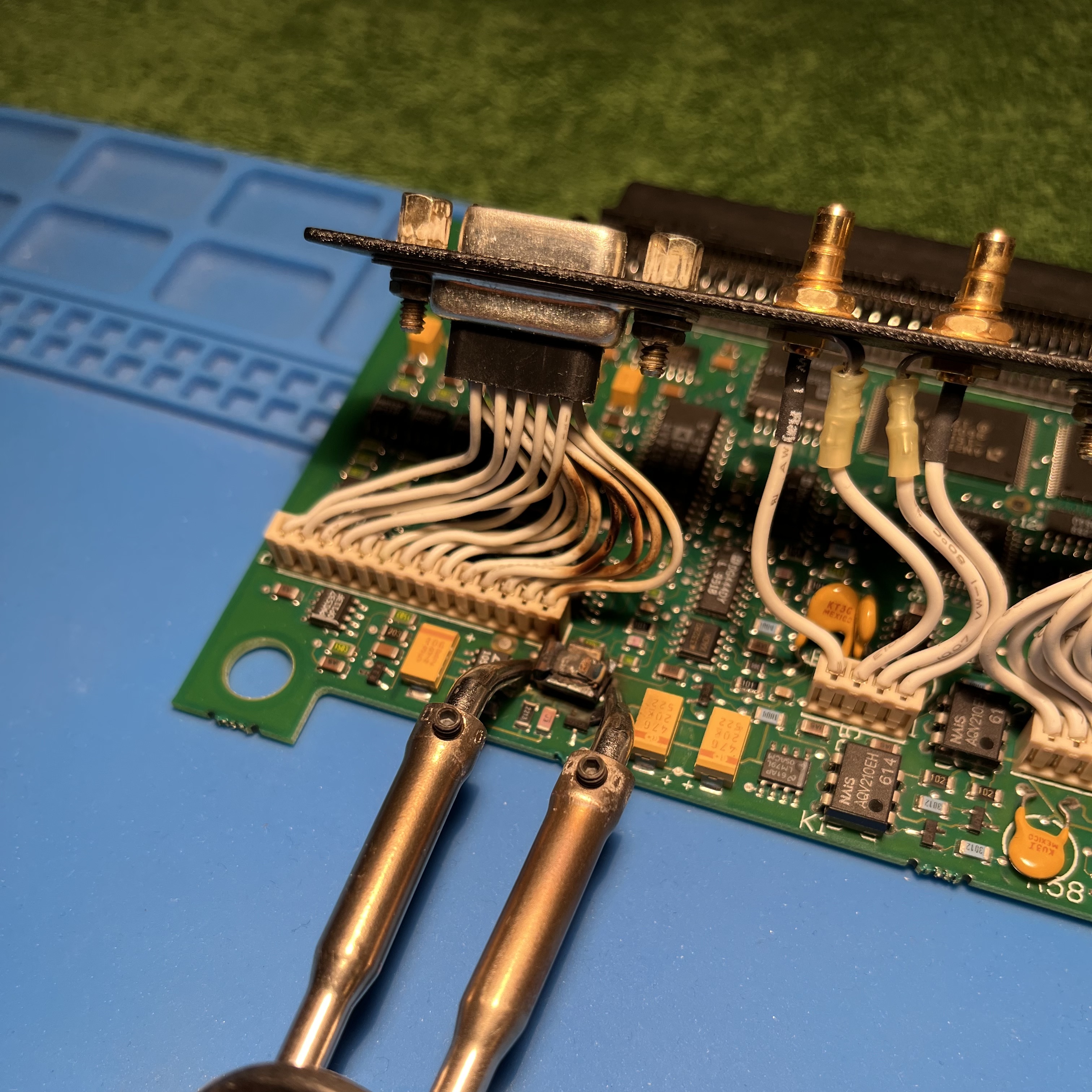
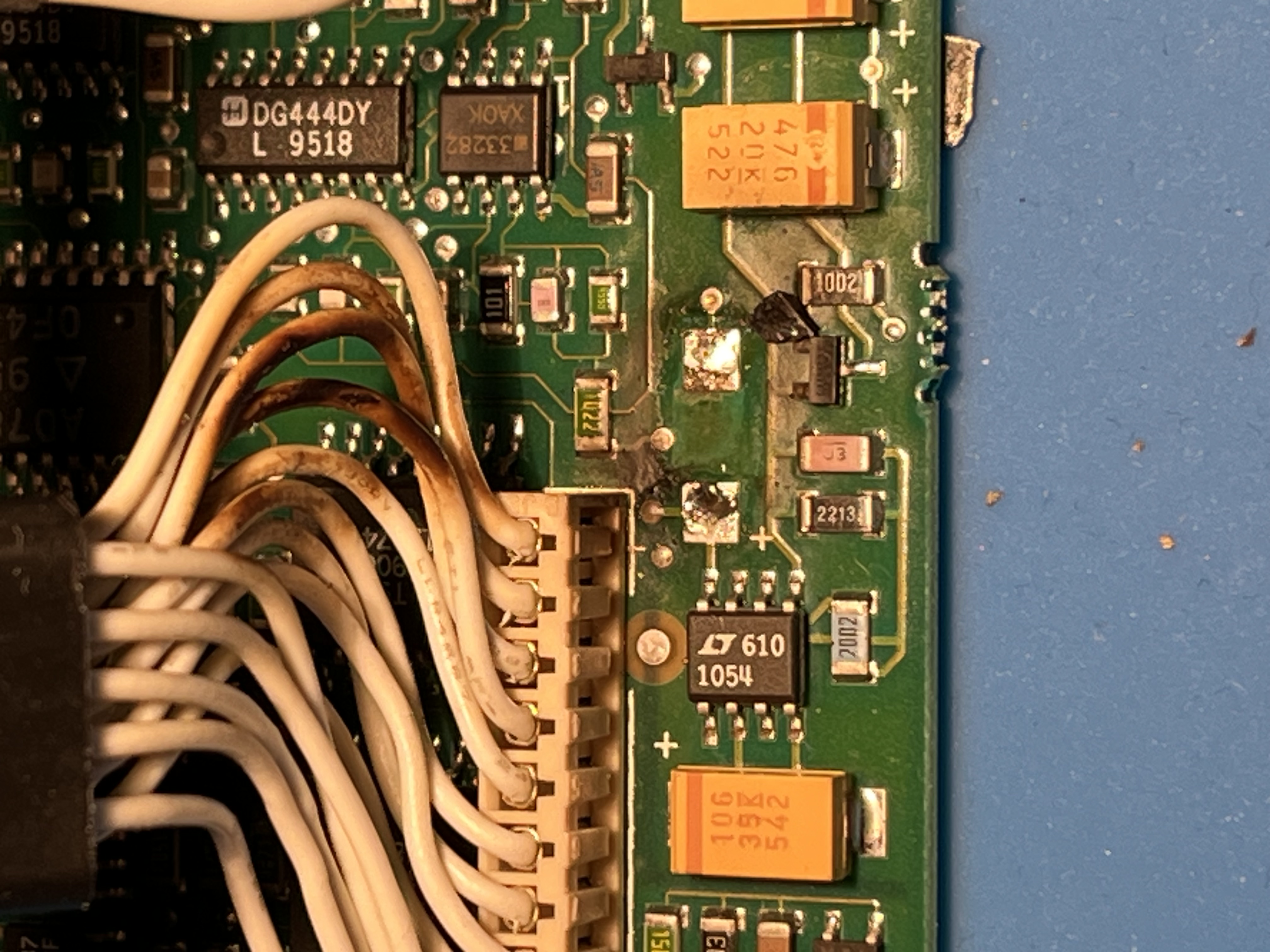
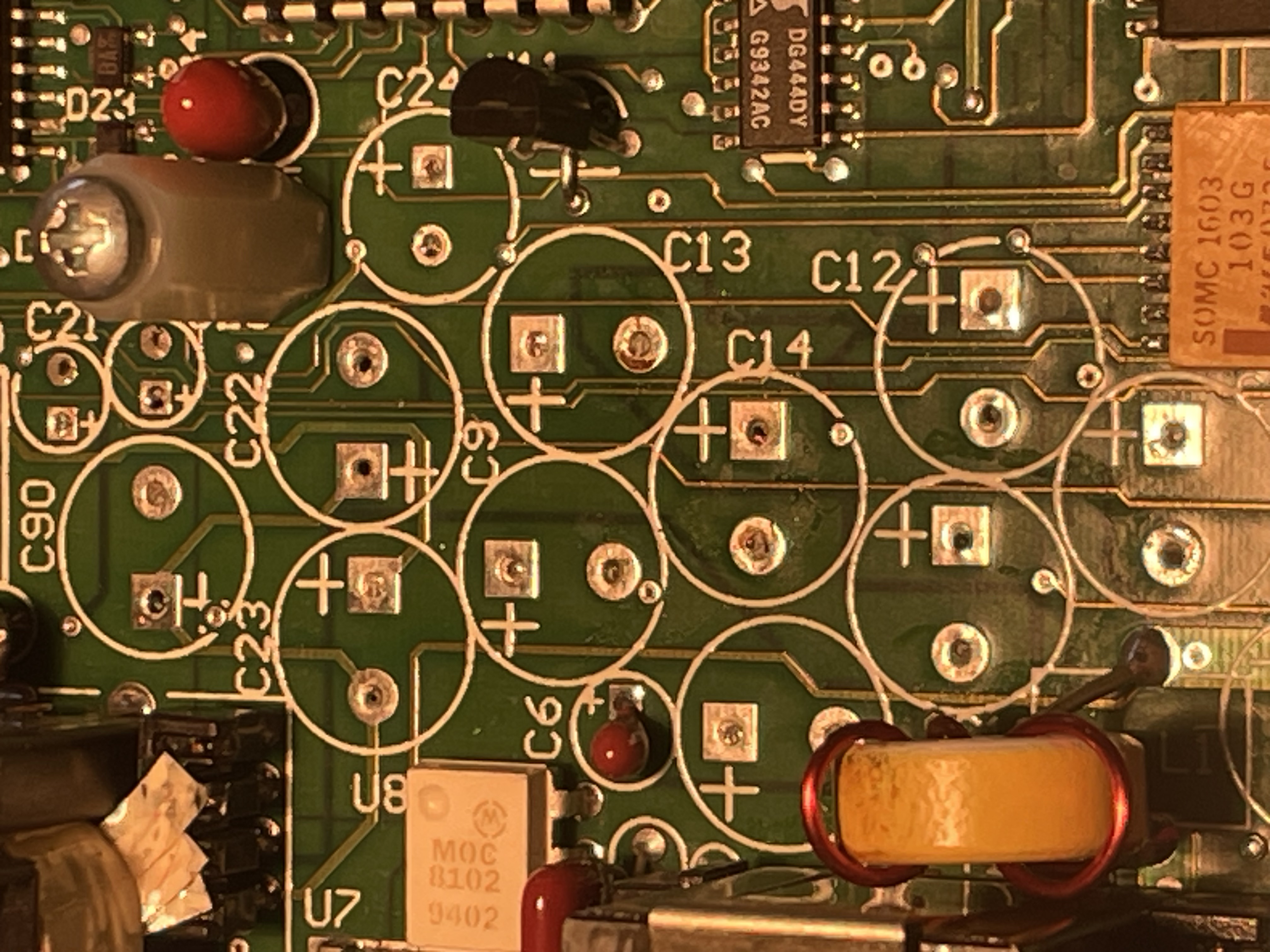
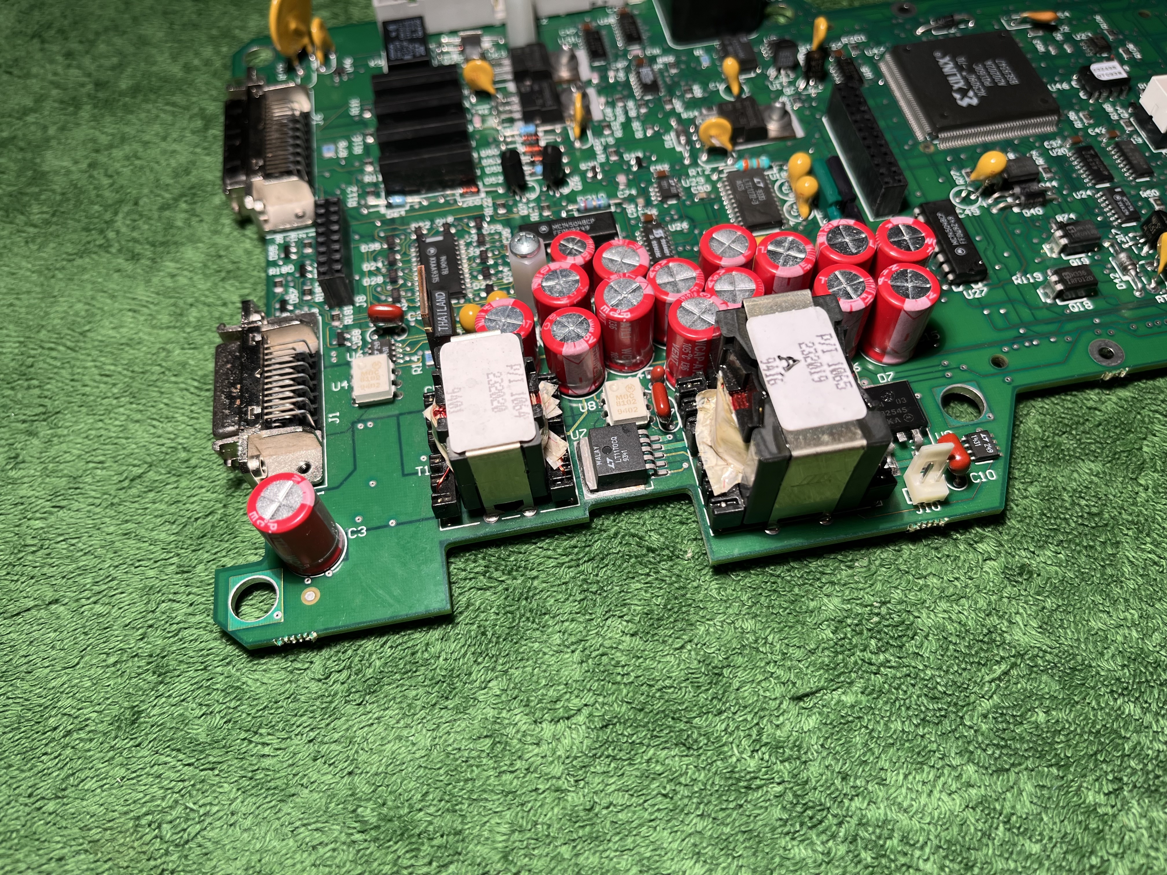
The first PCB has quite a few capacitors. They need to be swapped.
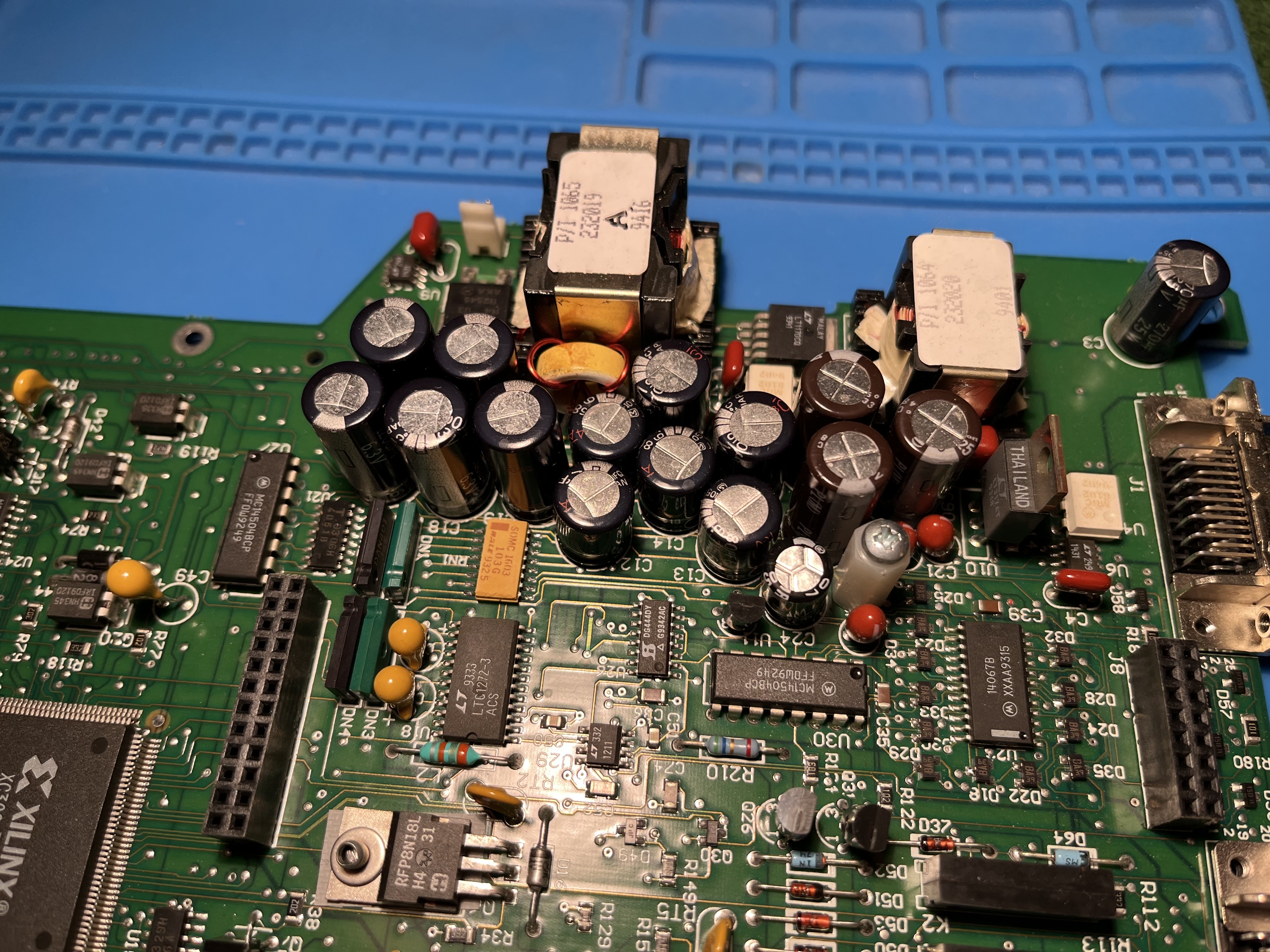
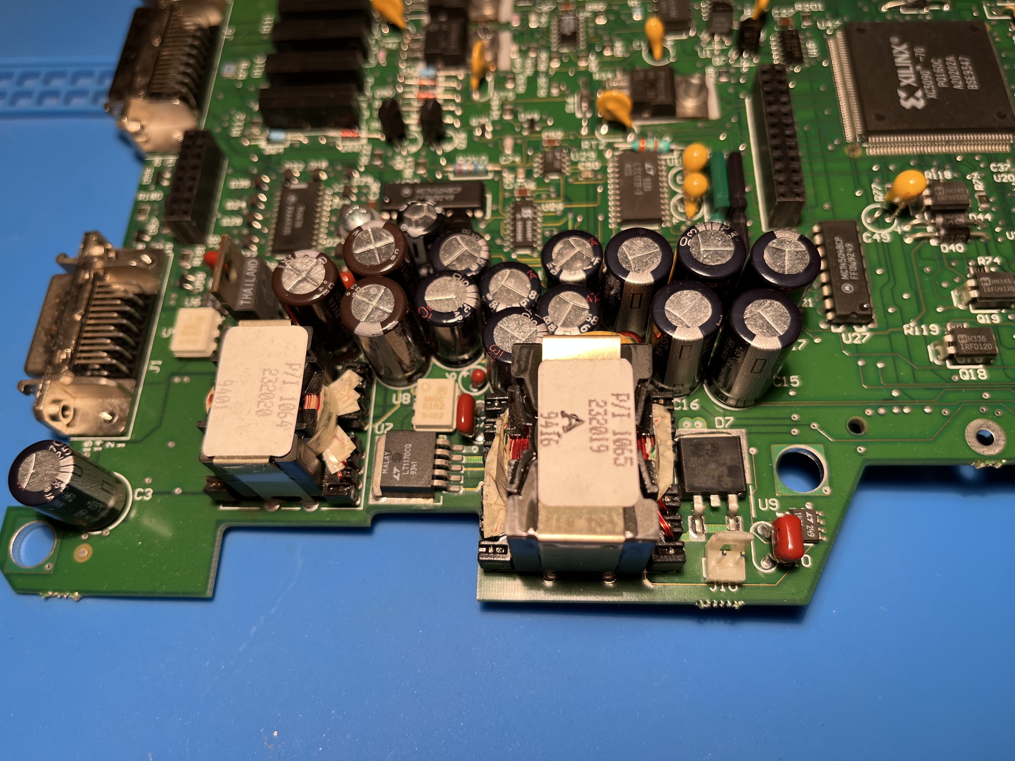
Allthough they dont look to bad, the PCB under the caps was not exactly clean.
All done and ready to roll. This may look easy but it sure is not. The DRB III’s PCBs are multilayered, making de-soldering extremely difficult. The risk of destroying a PCB is high and looking at the multi thousand $ pricepoint of these devices one should strongly consider really not doing this and rather send it to a specialist.
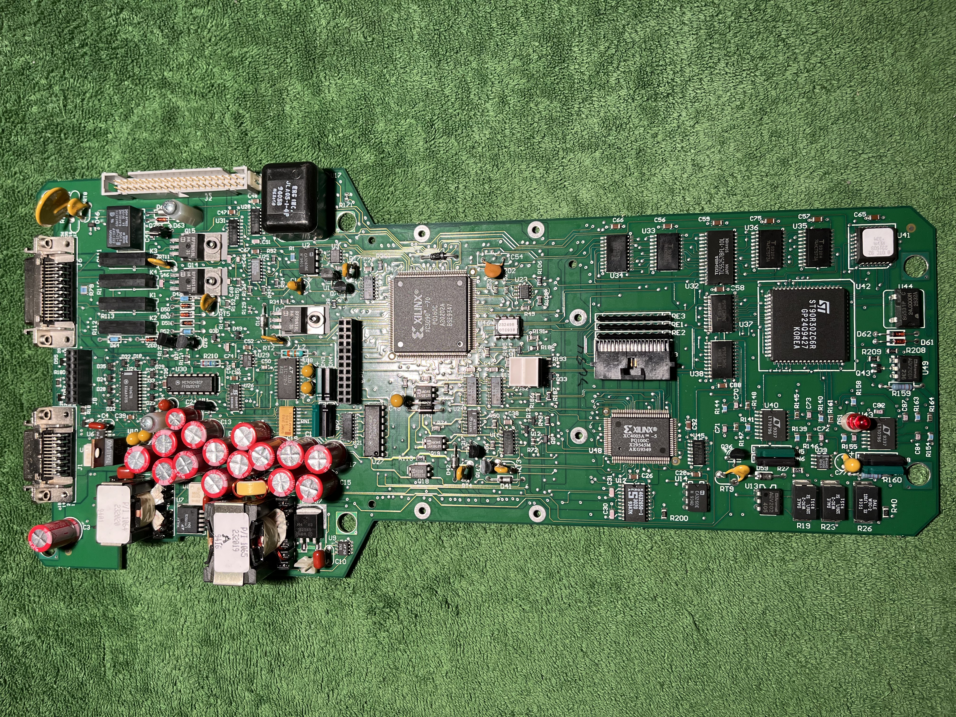
Ready to roll for another 30 years of service.